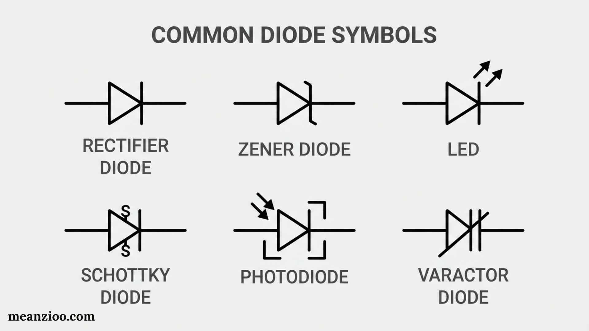
Diode symbols are graphical signs used in electrical and electronic schematics to identify different types of diodes and show their orientation in a circuit. Learning these symbols helps beginners and electronics students understand circuit diagrams, identify anode and cathode connections, and recognize specialized components such as Zener diodes, LEDs, Schottky diodes, and photodiodes.
The basic diode symbol represents a two-terminal semiconductor device that allows conventional current to flow primarily in one direction. Different diode types use variations of this basic symbol to show their special functions.
This guide explains common diode symbols, their names, meanings, polarity markings, schematic abbreviations, and practical uses in simple terms.
What Is a Diode Symbol?
A diode symbol is a standardized graphical representation of a diode used in an electrical schematic or circuit diagram.
A typical diode symbol contains two terminals and a distinctive bar or line representing the cathode. The opposite terminal is the anode.
The symbol communicates important information without requiring the designer to write a long description. By looking at it, you can determine:
- That the component is a diode
- Which terminal is the anode
- Which terminal is the cathode
- Whether it is a specialized diode
- How the component is oriented in the circuit
The exact appearance can vary slightly depending on the drawing standard, schematic software, or documentation.
Basic Diode Symbol

The standard PN-junction diode is represented by a diode-shaped symbol with a solid triangular-looking? More accurately, the conventional symbol consists of a triangle-free diode symbol formed by a triangular-looking?
For clarity, the standard schematic symbol is best understood as a triangle-free symbol with a filled/outlined triangular-looking? No. The standard diode symbol consists of a triangle-free arrowless diode shape: a triangle is not part of the standard symbol.
The key feature is the bar on the cathode side.
In a circuit diagram, the symbol can be rotated or flipped depending on the circuit design. Its orientation determines the direction of conventional current flow when the diode is forward biased.
Main Parts of the Standard Diode Symbol
A standard diode has two terminals:
- Anode (A)
- Cathode (K)
The line or bar in the symbol identifies the cathode.
This is one of the most important facts to remember when reading diode symbols:
The bar marks the cathode.
Diode Symbols and Names Chart
Here is a quick reference for common diode types.
| Diode Type | Main Symbol Feature | Main Function |
| PN-junction diode | Basic diode symbol | Rectification and switching |
| Zener diode | Modified cathode line | Voltage regulation |
| Schottky diode | Modified cathode marking | Fast switching and low voltage drop |
| LED | Arrows pointing outward | Produces light |
| Photodiode | Arrows pointing inward | Detects light |
| Varactor diode | Diode with capacitor-like plates | Variable capacitance |
| TVS diode | Protection-oriented diode symbol | Transient suppression |
| Laser diode | Light-emission arrows and special notation | Produces laser light |
| Tunnel diode | Modified diode symbol | Specialized high-speed circuits |
| PIN diode | Diode representing PIN structure | RF switching and detection |
These symbols are commonly encountered in electronics, although exact graphical conventions can differ.
Anode and Cathode in Diode Symbols
Understanding anode and cathode is essential before moving on to specialized diode symbols.
What Is the Anode?
The anode is one of the two terminals of a diode. In a normally forward-biased conventional diode, the anode is at a higher potential than the cathode.
What Is the Cathode?
The cathode is the terminal identified by the bar in the schematic symbol.
A useful memory trick is:
Bar = Cathode.
The same relationship often appears on the physical component, where a band or stripe identifies the cathode.
How to Identify Diode Polarity From a Symbol
To identify the polarity of a diode in a circuit diagram:
- Find the diode symbol.
- Look for the straight bar or cathode marking.
- The terminal connected to that bar is the cathode.
- The opposite terminal is the anode.
- Follow the circuit to determine how the diode is biased.
The diode symbol can be rotated. Therefore, do not assume that the cathode is always drawn on the right side. The bar itself is what identifies it.
How to Identify Polarity on a Physical Diode
A physical diode usually has a marking that corresponds to the cathode.
Depending on the component, this may be:
- A painted band
- A stripe
- A ring
- A printed marking
- A manufacturer-specific indicator
For many common through-hole diodes, the stripe or band indicates the cathode.
However, physical markings are not identical for every device. When working with an unfamiliar component, the manufacturer’s datasheet is the safest source for identifying polarity.
Standard PN-Junction Diode Symbol
The ordinary PN-junction diode is the basic symbol from which many specialized diode symbols are derived.
It represents a semiconductor device formed by a PN junction.
Standard diodes are commonly used for:
- AC-to-DC rectification
- Reverse-polarity protection
- Signal steering
- Switching
- Flyback protection
- Clamping
- General circuit protection
When you see the basic diode symbol without additional features, it usually indicates a standard diode.
Zener Diode Symbol
The Zener diode symbol resembles the standard diode symbol but has a distinctive modified cathode line.
This special marking distinguishes it from an ordinary PN-junction diode.
Zener diodes are designed to operate in reverse breakdown within their intended operating range.
Zener Diode Applications
They are commonly used for:
- Voltage regulation
- Voltage references
- Overvoltage limiting
- Signal clipping
- Protection circuits
Standard Diode vs. Zener Diode Symbol
The easiest difference to remember is the cathode marking.
Standard diode: straight cathode bar.
Zener diode: modified or bent cathode line.
The actual graphic should be checked against the schematic standard being used.
Schottky Diode Symbol
A Schottky diode uses a modified version of the normal diode symbol.
Its distinctive cathode marking helps distinguish it from a standard PN-junction diode.
Schottky diodes are known for relatively low forward voltage and fast switching characteristics.
Schottky Diode Applications
They are frequently used in:
- Switching power supplies
- DC-DC converters
- High-frequency circuits
- Power rectification
- Reverse-polarity protection
- Fast switching applications
The exact symbol details can vary by schematic convention, so the component label and datasheet can provide additional confirmation.
LED Symbol
An LED, or light-emitting diode, produces light when appropriately forward biased.
Its schematic symbol is based on the ordinary diode symbol but includes two arrows pointing away from the diode.
The outward arrows represent emitted light.
How to Recognize an LED Symbol
Look for:
- The normal diode symbol
- Two outward-pointing arrows
- Anode and cathode terminals
The arrows are the key feature that separates the LED symbol from an ordinary diode.
LED Applications
LEDs are used in:
- Indicator lamps
- Displays
- Lighting
- Automotive electronics
- Consumer devices
- Optical communication
Photodiode Symbol
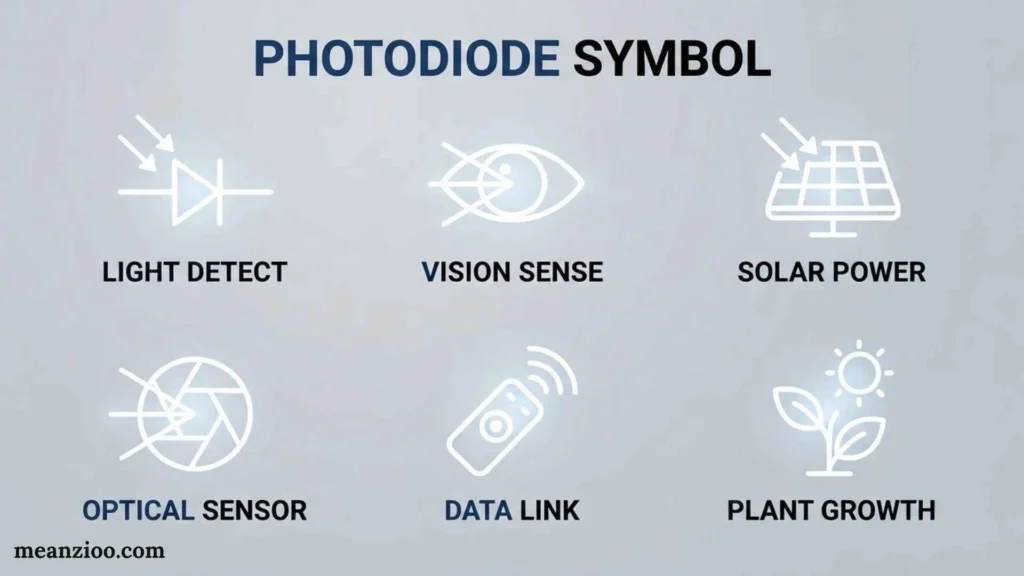
A photodiode is designed to respond to incoming light.
Its symbol resembles an LED but reverses the direction of the light arrows.
Photodiode = arrows pointing toward the diode.
This is a useful visual distinction.
Photodiode Applications
Photodiodes are used for:
- Light sensing
- Optical communication
- Remote-control receivers
- Measurement instruments
- Barcode systems
- Position and light detection
LED vs. Photodiode Symbols
The two symbols are easy to confuse until you remember the arrows.
| Device | Arrow Direction | Function |
| LED | Arrows point outward | Emits light |
| Photodiode | Arrows point inward | Detects light |
A simple memory trick is:
LED sends light out. Photodiode receives light in.
Varactor Diode Symbol
A varactor diode, also called a varicap diode, is a semiconductor device whose capacitance changes with applied reverse voltage.
Its symbol combines diode notation with capacitor-like plates.
The capacitor-style marking tells you that the device is being used for its voltage-dependent capacitance.
Varactor Diode Applications
Varactors are used in:
- Radio tuning
- RF circuits
- Frequency synthesizers
- Oscillators
- Communication systems
- Voltage-controlled frequency circuits
TVS Diode Symbol
A TVS diode stands for Transient Voltage Suppressor.
It is designed to protect circuits from short-duration voltage transients.
TVS devices may be unidirectional or bidirectional, and their schematic representation can vary.
They are commonly used for:
- Electrostatic discharge protection
- Switching transients
- Automotive protection
- Power-line transients
- Interface protection
A TVS symbol can resemble other protection-diode symbols, so the component reference and datasheet are useful for confirmation.
Laser Diode Symbol
A laser diode is a semiconductor device that emits coherent laser light.
Its symbol is related to the LED symbol and normally uses light-emission arrows to indicate optical output, along with notation identifying the laser device.
Laser diodes are used in:
- Fiber-optic communication
- Optical sensors
- Barcode readers
- Laser measurement equipment
- Optical storage systems
Tunnel Diode Symbol
A tunnel diode is a specialized semiconductor diode that uses quantum tunneling.
Its schematic representation is a modified diode symbol that distinguishes it from an ordinary PN-junction diode.
Tunnel diodes have been used in specialized:
- High-speed switching
- Oscillator
- Microwave
- RF
applications.
They are less common in everyday consumer electronics than ordinary diodes, LEDs, Zener diodes, and Schottky diodes.
PIN Diode Symbol
A PIN diode contains three semiconductor regions:
- P-type region
- Intrinsic region
- N-type region
The schematic representation is based on the diode symbol and may include additional notation depending on the drawing standard.
PIN diodes are commonly used in:
- RF switches
- RF attenuators
- Microwave circuits
- Photodetection
- High-frequency systems
Diode Symbols Used in Circuit Diagrams
Diode symbols are used throughout electronic schematics to show how components interact.
For example, a diode may appear next to:
- Resistors
- Capacitors
- Transistors
- Integrated circuits
- Transformers
- Batteries
- Switches
The diode’s orientation is important because it indicates its intended current direction.
Example: Rectifier Circuit
A rectifier circuit uses one or more diodes to convert AC into pulsating DC.
Common configurations include:
- Half-wave rectifier
- Full-wave rectifier
- Bridge rectifier
A bridge rectifier uses four diodes arranged so that current through the load remains in the desired direction during both halves of an AC cycle.
Diode Symbols in Electrical Schematics
Electrical and electronic schematics use symbols to communicate circuit functions efficiently.
When you see a diode symbol, examine:
- The basic diode shape.
- The cathode bar.
- Any additional arrows or markings.
- The component reference designator.
- The surrounding circuit.
For example, a diode labeled D1 may be the first diode in a circuit, while D2 may identify the second.
The exact reference designator depends on the schematic’s conventions.
Common Diode Schematic Abbreviations
Several abbreviations can appear alongside diode symbols.
| Abbreviation | Meaning |
| D | Diode |
| LED | Light-Emitting Diode |
| ZD | Zener diode in some schematics |
| Z | Zener-related designation in some conventions |
| PD | Photodiode in some schematics |
| TVS | Transient Voltage Suppressor |
| A | Anode |
| K | Cathode |
| V<sub>F</sub> | Forward voltage |
| V<sub>R</sub> | Reverse voltage |
| I<sub>F</sub> | Forward current |
| I<sub>R</sub> | Reverse current |
Reference designators are not completely universal, so a schematic’s legend or documentation should be checked when necessary.
Diode Symbol vs. Diode Circuit Notation
A symbol is the graphical representation of the component.
Circuit notation can include the component’s reference designator, value, model number, polarity information, or other labels.
For example, a schematic might contain a diode symbol labeled D1.
Here:
- The symbol identifies the component type and polarity.
- D1 identifies the particular component within the circuit.
- Additional text may provide the part number or specifications.
This distinction becomes important when reading complex schematics.
How Diodes Work in Forward Bias
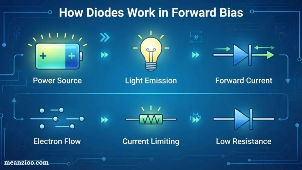
In forward bias, the diode is connected so that it can conduct current.
For a conventional silicon PN-junction diode, the forward voltage is often around 0.7 V under commonly encountered operating conditions, but the actual value depends on current, temperature, and the particular diode.
Schottky diodes generally have a lower forward voltage than many conventional silicon diodes.
The symbol itself does not give the exact forward voltage. That information comes from the component’s specifications.
How Diodes Work in Reverse Bias
In reverse bias, the diode normally blocks most current.
However, real diodes are not perfect switches. A small reverse leakage current can exist.
If the reverse voltage exceeds a device’s specified breakdown rating, significant current can flow. Some diodes, such as Zener diodes, are specifically designed to operate in controlled reverse breakdown.
This is why diode type and rating matter when designing a circuit.
How to Read Any Diode Symbol
If you encounter an unfamiliar diode symbol, use this checklist:
Identify the Base Symbol
Determine whether it is based on a normal diode.
Look for Extra Features
Check for:
- Arrows
- Modified cathode lines
- Capacitor plates
- Special markings
Find the Cathode
Locate the bar or cathode indicator.
Identify the Anode
The opposite terminal is the anode.
Check the Reference Designator
Look for labels such as D1, D2, LED1, or another circuit-specific designation.
Consult the Datasheet
If the symbol is unfamiliar or the exact component matters, verify it using the manufacturer’s documentation.
Most Important Diode Symbols to Remember
If you are studying electronics, start with these common symbols:
- Standard diode — basic one-way semiconductor device.
- Zener diode — modified cathode line for controlled reverse-breakdown applications.
- Schottky diode — distinctive symbol for a fast, low-forward-voltage diode.
- LED — diode with outward-pointing light arrows.
- Photodiode — diode with inward-pointing light arrows.
- Varactor diode — diode with capacitor-like markings.
- TVS diode — transient protection device.
- Laser diode — light-emitting diode symbol with laser-related notation.
- Tunnel diode — specialized diode symbol.
- PIN diode — diode used extensively in RF and sensing applications.
Common Mistakes When Reading Diode Symbols
Mistake 1: Reversing the Cathode and Anode
The cathode is identified by the bar on the standard diode symbol.
Mistake 2: Confusing LED and Photodiode Symbols
Remember:
Outward arrows = emitted light.
Inward arrows = incoming light.
Mistake 3: Assuming Every Diode Is the Same
A Zener, Schottky, TVS, LED, and photodiode can behave very differently.
Mistake 4: Ignoring Component Ratings
The symbol does not tell you the diode’s maximum voltage, current, power, or switching speed.
Mistake 5: Assuming Physical Markings Are Identical
Many diodes use a stripe to indicate the cathode, but not every component follows exactly the same physical marking convention.
Mistake 6: Relying Only on an ASCII Symbol
Text representations can be misleading because a diode symbol can be rotated and may not display correctly in plain text. For accurate identification, use the actual schematic symbol or datasheet.
Frequently Asked Questions About Diode Symbols
What is the symbol for a diode?
The standard diode symbol is a two-terminal semiconductor symbol with a bar identifying the cathode. The symbol may be rotated depending on the circuit.
Which side of a diode symbol is the cathode?
The side containing the bar or cathode line is the cathode.
How do I identify the anode?
The anode is the terminal opposite the cathode bar.
What does the bar on a diode symbol mean?
The bar identifies the cathode.
What is the symbol for an LED?
An LED uses the basic diode symbol with arrows pointing outward, indicating emitted light.
What is the symbol for a photodiode?
A photodiode uses a diode symbol with arrows pointing toward the diode, indicating incoming light.
What is the difference between a diode and a Zener diode symbol?
A Zener diode has a modified cathode line, while a standard diode normally has a straight cathode bar.
What does a Schottky diode symbol look like?
A Schottky diode is based on the standard diode symbol but has a distinctive cathode-side modification.
What does H mean on a diode symbol?
There is no universal diode-symbol meaning for the letter H by itself. Its meaning depends on the schematic or component documentation.
How do I identify a diode on a circuit board?
Look for the component’s reference marking, physical band or stripe, PCB polarity marking, and the corresponding schematic or datasheet.
What is the difference between a diode symbol and a diode marking?
The diode symbol appears in a schematic. A physical marking appears on the actual component and may identify polarity, part number, or other information.
Are diode symbols standardized?
Many common diode symbols are standardized and widely recognized, but graphical details and reference designators can vary between standards, manufacturers, and schematic software.
Final Thoughts
Understanding diode symbols is an essential skill for anyone learning electronics or reading circuit diagrams. The standard diode symbol identifies the component and shows its polarity, with the bar marking the cathode and the opposite terminal being the anode.
Specialized diode symbols build on this basic idea. A Zener diode has a modified cathode marking, an LED has outward-pointing light arrows, a photodiode has inward-pointing arrows, and a varactor diode uses capacitor-like markings. Schottky, TVS, laser, tunnel, and PIN diodes also have distinctive schematic representations.
Once you understand the basic diode symbol, anode, cathode, polarity, and the visual differences between common diode types, reading electronic schematics becomes much easier. For unfamiliar symbols or physical components, always verify the exact device and polarity using the relevant circuit documentation or manufacturer datasheet.

Hi, I’m Charlotte Hayes. I love writing about the newest English slang, pop culture phrases, and digital communication. I spend my time exploring how language evolves across social media, gaming, and everyday conversations. I enjoy sharing easy-to-understand guides that help learners keep up with modern English. My goal is to make every article useful, accurate, and enjoyable for readers around the world.
Books:
- Everyday Slang Dictionary
- Fluent Through Informal English
 Ryan Mitchell