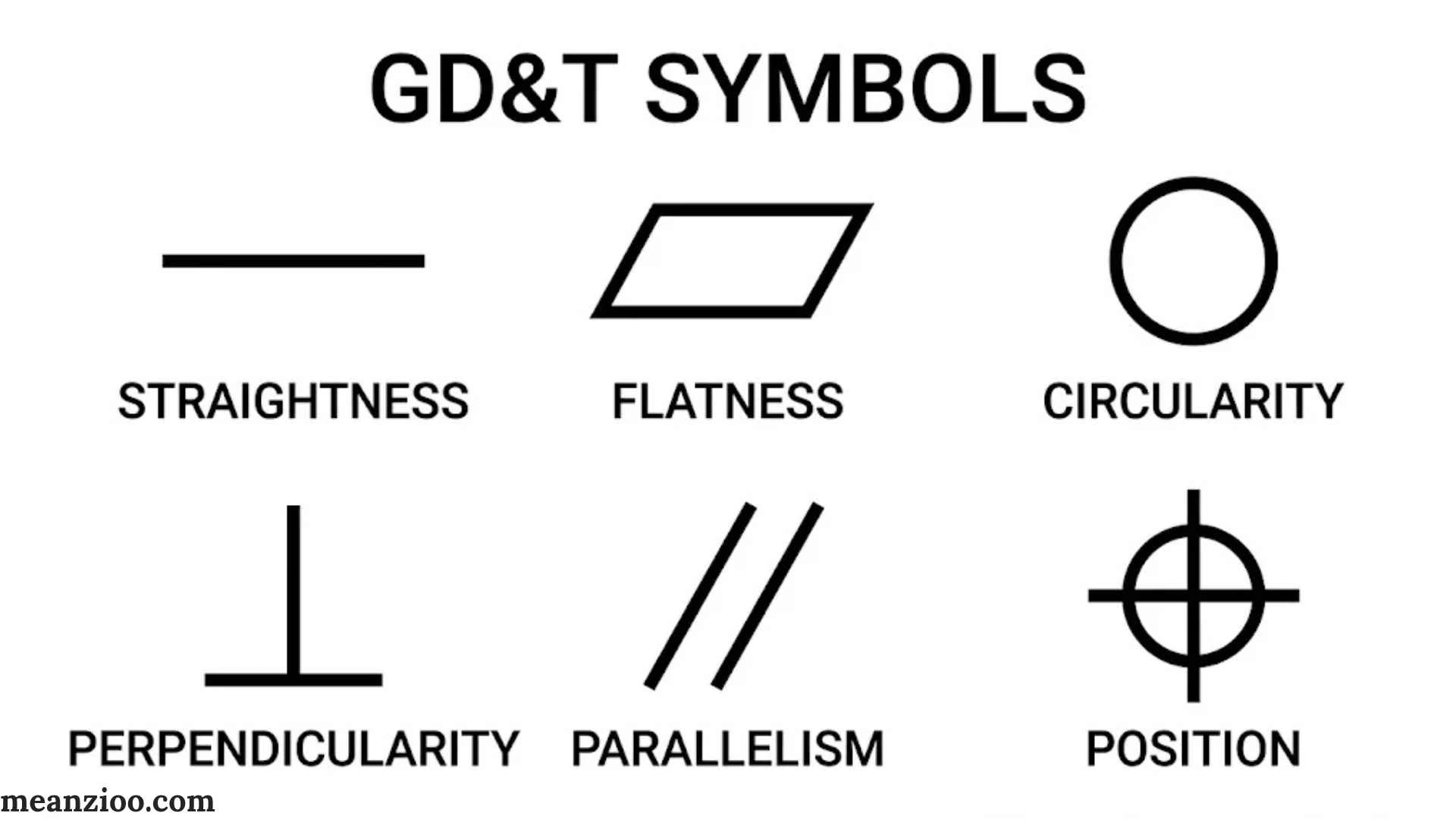
Geometric Dimensioning and Tolerancing (GD&T) is a system engineers use to describe the allowable variation in a manufactured part. It uses standardized symbols to communicate requirements for shape, orientation, position, location, and other geometric characteristics. These symbols help designers, machinists, and inspectors understand exactly how a component should be manufactured and measured.
If you’re looking for a complete GD&T symbols chart, this guide covers the most commonly used geometric tolerancing symbols, their names, meanings, and practical applications. You’ll also find tolerance modifiers, profile symbols, concentricity, and examples of feature control frames.
Whether you’re reading an engineering drawing, preparing a manufacturing specification, or inserting GD&T symbols in Excel, understanding these characters can make technical information much easier to interpret. Use the reference tables below to find the symbols you need.
GD&T Symbols Cheat Sheet
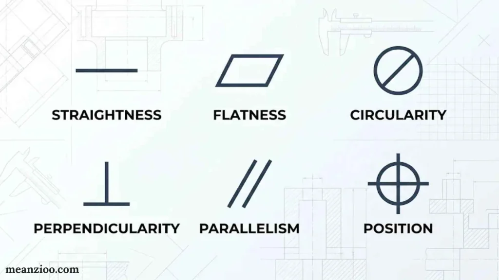
A GD&T cheat sheet gives you a quick reference to the symbols used in engineering drawings. Each symbol represents a particular geometric requirement and communicates how much variation a feature can have.
The following table covers the main geometric characteristics found in ASME Y14.5.
| Symbol | GD&T Symbol Name | Category |
| ⏤ | Straightness | Form |
| ⏥ | Flatness | Form |
| ○ | Circularity (Roundness) | Form |
| ⌭ | Cylindricity | Form |
| ∥ | Parallelism | Orientation |
| ⟂ | Perpendicularity | Orientation |
| ∠ | Angularity | Orientation |
| ⌖ | Position | Location |
| ◎ | Concentricity (Legacy) | Location |
| ⌯ | Symmetry (Legacy) | Location |
| ⌒ | Profile of a Line | Profile |
| ⌓ | Profile of a Surface | Profile |
| ↗ | Circular Runout | Runout |
| ⌰ | Total Runout | Runout |
Important: The concentricity and symmetry controls were removed from ASME Y14.5-2018. They may still appear on older engineering drawings and documents following earlier standards. The current ASME standard is Y14.5-2018 (R2024).
ASME+2
The symbols above provide a starting point, but their actual requirements depend on the tolerance value, datum references, and modifiers shown in the feature control frame.
Tolerance Symbols
Tolerance symbols communicate the acceptable variation in a manufactured component. They help establish how much a feature can deviate from its intended geometry without affecting the part’s function.
In GD&T, geometric tolerances are organized into several categories.
Form Tolerance Symbols
Form controls describe the shape of individual features. They generally do not require datum references.
| Symbol | Name | Meaning |
| ⏤ | Straightness | Controls how straight a line or derived median line must be. |
| ⏥ | Flatness | Controls how flat a surface must be. |
| ○ | Circularity | Controls the roundness of individual circular cross-sections. |
| ⌭ | Cylindricity | Controls the overall form of a cylindrical surface. |
For example, a flatness requirement ensures that a machined surface stays between two parallel planes separated by the specified tolerance.
Orientation Tolerance Symbols
Orientation controls describe how one feature must be aligned relative to a datum.
| Symbol | Name | Meaning |
| ∥ | Parallelism | Keeps a surface or feature parallel to a datum. |
| ⟂ | Perpendicularity | Controls a 90-degree relationship to a datum. |
| ∠ | Angularity | Controls a specified angle relative to a datum. |
These controls are particularly useful when manufacturing brackets, mounting surfaces, shafts, and mechanical assemblies.
Location Tolerance Symbols
Location controls specify where a feature should be positioned relative to theoretically exact dimensions and applicable datums.
| Symbol | Name | Meaning |
| ⌖ | Position | Controls the location of a feature or pattern. |
| ◎ | Concentricity | Controls derived median points relative to a datum axis in legacy drawings. |
| ⌯ | Symmetry | Controls a derived median plane in legacy drawings. |
Position is widely used for controlling holes, pins, and bolt patterns.
Runout Tolerance Symbols
Runout controls describe the variation of a rotating surface relative to a datum axis.
| Symbol | Name | Meaning |
| ↗ | Circular Runout | Controls variation at individual circular cross-sections. |
| ⌰ | Total Runout | Controls variation across the entire indicated surface. |
Runout requirements are common in shafts, rotating components, bearings, and other precision-machined parts.
GD&T Symbols in Excel
Excel can help you organize engineering specifications, create inspection sheets, and maintain manufacturing records. You can insert GD&T symbols into cells, headings, and technical notes.
However, not every GD&T character is available through the standard Excel symbol library. Some symbols may also display differently depending on the selected font.
Method 1: Insert Symbols From Excel
Follow these steps to insert an available symbol:
- Open your Excel workbook.
- Select the cell where you want the symbol.
- Click the Insert tab.
- Select Symbol from the Symbols section.
- Choose a suitable font and browse the available characters.
- Select the required symbol and click Insert.
You can repeat these steps to add different geometric symbols to your spreadsheet.
Method 2: Copy and Paste GD&T Symbols
Copying symbols directly is often quicker than searching through Excel’s character library.
| Symbol | Name | Copy |
| ⏤ | Straightness | ⏤ |
| ⏥ | Flatness | ⏥ |
| ○ | Circularity | ○ |
| ⌭ | Cylindricity | ⌭ |
| ∥ | Parallelism | ∥ |
| ⟂ | Perpendicularity | ⟂ |
| ∠ | Angularity | ∠ |
| ⌖ | Position | ⌖ |
| ⌒ | Profile of a Line | ⌒ |
| ⌓ | Profile of a Surface | ⌓ |
| ↗ | Circular Runout | ↗ |
| ⌰ | Total Runout | ⌰ |
Select the character you need, copy it, and paste it into your spreadsheet.
Method 3: Use Unicode and Character Codes
Some symbols have Unicode code points that you can use to identify or insert them.
For example:
- ⟂ — U+27C2, Perpendicular.
- ∥ — U+2225, Parallel.
- ∠ — U+2220, Angle.
- ○ — U+25CB, White Circle.
- ⌒ — U+2312, Arc.
- ⌓ — U+2313, Segment.
These are Unicode character identities, not necessarily official GD&T names. The engineering meaning comes from the applicable drawing standard and its context.
Excel tip: If a character appears as an empty box, try changing the font. A font may support ordinary mathematical characters without containing every specialized drafting glyph. For professional drawings, use Excel as a reference or documentation tool rather than relying on plain text to replace a correctly formatted feature control frame.
Concentricity Symbol
The concentricity symbol (◎) represents a geometric control that relates the derived median points of a cylindrical or spherical feature to a datum axis.
It is commonly associated with components that have multiple circular features sharing a common center or axis.
◎
Concentricity Symbol
Copy this symbol: ◎
Copy symbol
What Does Concentricity Control?
Concentricity controls the location of derived median points relative to a datum axis. These median points are determined from opposed surface elements of the controlled feature.
For example, imagine a stepped shaft with two cylindrical sections. A concentricity requirement on an older drawing may specify how closely the median points of one section must align with the reference axis.
Is Concentricity Still Used in GD&T?
There is an important standards-related detail to understand.
ASME Y14.5-2018 removed concentricity as a recognized geometric characteristic. The symbol may still appear on legacy drawings based on earlier editions.
For new designs following the 2018 ASME standard, engineers generally consider position or runout controls when those controls meet the functional requirement. The correct choice depends on what the design actually needs to control.
app.gdandtbasics.com+2
GD&T Modifier Symbols
GD&T modifiers add information to a geometric tolerance or datum reference. They help explain how a tolerance zone behaves under specific material conditions or other requirements.
Here are several commonly encountered modifier symbols:
| Symbol | Modifier Name | Meaning |
| Ⓜ | Maximum Material Condition (MMC) | Applies a requirement at the maximum material condition. |
| Ⓛ | Least Material Condition (LMC) | Applies a requirement at the least material condition. |
| Ⓟ | Projected Tolerance Zone | Extends a tolerance zone beyond the surface of a feature. |
| Ⓕ | Free State | Applies a requirement in the free, unrestrained state. |
| Ⓣ | Tangent Plane | Specifies a tangent plane requirement. |
| Ⓤ | Unequally Disposed Profile | Controls the unequal distribution of a profile tolerance zone. |
Maximum Material Condition (MMC)
MMC describes the condition in which a feature contains the greatest amount of material within its permitted size limits.
For example:
- A hole has MMC at its smallest permitted diameter.
- A shaft has MMC at its largest permitted diameter.
When applicable, a geometric tolerance at MMC can provide additional allowable variation as the feature departs from its maximum material condition. This additional allowance is commonly called bonus tolerance.
Least Material Condition (LMC)
LMC represents the condition containing the least amount of material.
For example, a hole reaches LMC at its largest permitted diameter, while a shaft reaches LMC at its smallest permitted diameter.
This modifier can help protect minimum wall thickness or other design requirements.
Projected Tolerance Zone
The projected tolerance zone modifier is useful when a fastener or pin extends beyond the surface of a component.
It controls the permitted variation over a specified projected distance, helping prevent interference during assembly.
Free State Modifier
The free state modifier applies when a flexible component must be evaluated without external restraint.
This is particularly relevant to thin or flexible manufactured parts that may change shape under clamping or inspection forces.
Unequally Disposed Profile Modifier
The unequally disposed profile modifier controls how a profile tolerance zone is distributed around the theoretically exact profile.
Instead of distributing the tolerance equally on both sides, the designer can specify a different allocation.
Remember that modifiers have specific application rules. Not every modifier can accompany every geometric characteristic.
GD&T Symbols Profile of a Surface
The profile of a surface symbol (⌓) controls the three-dimensional contour of a surface. It ensures that the actual surface remains within a specified tolerance zone around its theoretically exact shape.
This control is useful for complex components that cannot be adequately described through simple dimensions.
⌓
Profile of a Surface
Copy this symbol: ⌓
Copy symbol
What Does Profile of a Surface Control?
It controls the entire specified three-dimensional surface rather than just one cross-sectional line.
The tolerance zone is established around the theoretically exact profile. The actual surface must remain within the permitted boundaries.
For example, consider an automotive body panel with a curved outer surface. A profile tolerance can help ensure that the manufactured panel follows the intended contour.
Common Applications
Profile of a surface is frequently useful for:
- Automotive body panels and exterior components.
- Turbine blades and aerodynamic surfaces.
- Molded plastic components.
- Cast metal parts.
- Complex machined contours.
- Product housings with curved surfaces.
Profile of a Surface vs. Profile of a Line
These two controls look similar but serve different purposes.
| Feature | Profile of a Line | Profile of a Surface |
| Symbol | ⌒ | ⌓ |
| Control | Two-dimensional line elements | Three-dimensional surface |
| Application | Selected cross-sections | Entire specified surface |
| Typical use | Contour of an individual section | Complex curved component |
A profile tolerance may also reference datums to control the location and orientation of a surface, depending on how the feature control frame is constructed.
NORAMARK+2
GDT Symbols
GDT is a commonly used shortened search term for GD&T, which stands for Geometric Dimensioning and Tolerancing.
These symbols form a visual language for communicating engineering requirements. They tell manufacturers what geometric characteristics to control and help inspectors determine whether a finished part meets its design specifications.
The main symbol groups include:
- Form: Straightness, flatness, circularity, and cylindricity.
- Orientation: Parallelism, perpendicularity, and angularity.
- Location: Position and legacy controls such as concentricity and symmetry.
- Profile: Profile of a line and profile of a surface.
- Runout: Circular runout and total runout.
A geometric characteristic symbol usually appears in the first compartment of a feature control frame. Additional compartments communicate the tolerance value and any applicable datum references or modifiers.
Understanding these groups makes it easier to read technical drawings without memorizing every symbol individually.
GDT Symbols Chart
A GD&T symbols chart provides a visual reference for identifying geometric characteristics and understanding their purposes.
The following expanded chart includes symbol names, categories, and practical applications.
| Symbol | Name | Category | Common Application |
| ⏤ | Straightness | Form | Shafts and straight edges |
| ⏥ | Flatness | Form | Machined mounting surfaces |
| ○ | Circularity | Form | Circular cross-sections |
| ⌭ | Cylindricity | Form | Cylindrical components |
| ∥ | Parallelism | Orientation | Parallel faces and axes |
| ⟂ | Perpendicularity | Orientation | Right-angle surfaces |
| ∠ | Angularity | Orientation | Angled surfaces |
| ⌖ | Position | Location | Holes and bolt patterns |
| ⌒ | Profile of a Line | Profile | Two-dimensional contours |
| ⌓ | Profile of a Surface | Profile | Three-dimensional contours |
| ↗ | Circular Runout | Runout | Rotating surfaces |
| ⌰ | Total Runout | Runout | Entire rotating surfaces |
| ◎ | Concentricity | Legacy Location | Older precision drawings |
| ⌯ | Symmetry | Legacy Location | Older centered features |
How to Read a GD&T Chart
When using a chart, look beyond the symbol itself. A geometric control communicates different information depending on its tolerance value and references.
Check these details:
- Geometric characteristic: Identify the symbol in the first compartment.
- Tolerance value: Find the permitted geometric variation.
- Diameter symbol: Check whether the tolerance zone is cylindrical.
- Material condition: Look for applicable modifiers such as MMC or LMC.
- Datum references: Identify the reference features used to establish the tolerance zone.
A chart is useful for quick identification, but the applicable engineering standard remains the authority for interpreting a drawing.
GD&T Basics+2
GDT Symbols and Meanings
Understanding GD&T symbols and their meanings helps you interpret manufacturing requirements more accurately.
Here are some practical examples of what these symbols communicate.
| Symbol | Meaning | Simple Explanation |
| ⏤ | Straightness | A line or derived median line must remain straight within the tolerance. |
| ⏥ | Flatness | A surface must remain sufficiently flat. |
| ○ | Circularity | Each circular cross-section must maintain the required roundness. |
| ⌭ | Cylindricity | The complete cylindrical surface must maintain its specified form. |
| ∥ | Parallelism | A feature must remain parallel to a datum. |
| ⟂ | Perpendicularity | A feature must maintain a 90-degree relationship to a datum. |
| ∠ | Angularity | A feature must maintain a specified angle. |
| ⌖ | Position | A feature must remain within its permitted location zone. |
| ⌒ | Profile of a Line | A specified line contour must remain within its tolerance zone. |
| ⌓ | Profile of a Surface | A complete surface contour must meet its profile requirement. |
| ↗ | Circular Runout | A rotating cross-section must stay within the permitted runout. |
| ⌰ | Total Runout | The entire controlled surface must meet the runout requirement. |
Understanding Datum Symbols
Datums are important reference points, axes, or planes used to establish a coordinate system for geometric measurements.
Datum identifiers commonly use capital letters inside rectangular frames.
For example:
- A — Primary datum.
- B — Secondary datum.
- C — Tertiary datum.
The letters themselves are identifiers rather than fixed geometric characteristics. Their meaning depends on the features selected as datums in the engineering drawing.
A feature control frame referencing A, B, and C establishes a specific reference sequence. The order matters because each datum can constrain different degrees of freedom.
All GDT Symbols
For a broader reference, it helps to separate geometric characteristics from other symbols used in technical drawings.
The following collections cover the main GD&T controls, modifiers, and supporting characters.
Form and Geometry Symbols
- ⏤ — Straightness
- ⏥ — Flatness
- ○ — Circularity
- ⌭ — Cylindricity
Orientation Symbols
- ∥ — Parallelism
- ⟂ — Perpendicularity
- ∠ — Angularity
Location Symbols
- ⌖ — Position
- ◎ — Concentricity (Legacy)
- ⌯ — Symmetry (Legacy)
Profile and Runout Symbols
- ⌒ — Profile of a Line
- ⌓ — Profile of a Surface
- ↗ — Circular Runout
- ⌰ — Total Runout
Additional GD&T Characters
| Symbol | Name | Purpose |
| Ø | Diameter | Identifies a diameter dimension or cylindrical tolerance zone. |
| R | Radius | Identifies a radius dimension. |
| Ⓜ | MMC | Maximum material condition modifier. |
| Ⓛ | LMC | Least material condition modifier. |
| Ⓟ | Projected Zone | Projected tolerance zone modifier. |
| Ⓕ | Free State | Free state modifier. |
| Ⓤ | Unequally Disposed | Unequally disposed profile modifier. |
| A, B, C | Datum Identifiers | Identify datum references. |
A note about character accuracy: Some specialized drafting symbols may not display consistently in ordinary text fonts. Their appearance can also differ between CAD applications and standards. The table is a convenient reference, not a substitute for an approved engineering symbol library.
GDT Symbols Explained
The easiest way to understand GD&T is to learn how symbols work together rather than studying them individually.
Most geometric tolerance requirements appear inside a rectangular structure called a feature control frame (FCF). This frame communicates the geometric characteristic, tolerance value, and applicable datum references.
Understanding a Feature Control Frame
A typical feature control frame may contain three main types of information:
| Section | Information | Example |
| First compartment | Geometric characteristic | ⌖ |
| Second compartment | Tolerance value | Ø0.10 |
| Remaining compartments | Datum references | A, B, C |
For example, a position tolerance might appear as:
Example Feature Control Frame
⌖
Ø0.10
A
B
C
Simplified illustrative feature control frame
In this example:
- ⌖ identifies position as the geometric characteristic.
- Ø indicates a cylindrical tolerance zone.
- 0.10 specifies the tolerance value.
- A, B, and C identify the referenced datums.
The exact interpretation also depends on the drawing’s basic dimensions, applicable modifiers, and governing standard.
Why Are GD&T Symbols Important?
GD&T symbols help different teams communicate manufacturing requirements consistently.
They offer several practical benefits:
- Clearer engineering drawings: Symbols communicate geometric requirements without lengthy descriptions.
- Better manufacturing accuracy: Machinists can understand the intended shape and relationships between features.
- Consistent inspection: Quality teams can evaluate parts against defined geometric requirements.
- Improved assembly: Proper controls help components fit and function together.
- Reduced ambiguity: Standardized symbols provide a shared technical language.
GDT Symbols Meaning

People often search for GD&T symbol meanings because engineering drawings can contain unfamiliar characters and abbreviations.
The key is to understand that a symbol describes a geometric requirement, while the surrounding information explains how that requirement applies.
For example, the perpendicularity symbol (⟂) does not simply mean that two surfaces should form a right angle. It identifies a specific geometric control that establishes a tolerance zone relative to a datum.
Similarly, flatness (⏥) controls a surface independently of a datum, while parallelism (∥) establishes a relationship with a reference feature.
Here are a few useful distinctions:
| Similar Symbols | Main Difference |
| ⏥ Flatness vs. ∥ Parallelism | Flatness controls surface form; parallelism controls orientation relative to a datum. |
| ○ Circularity vs. ⌭ Cylindricity | Circularity controls individual circular sections; cylindricity controls the complete cylindrical surface. |
| ⌒ Profile of a Line vs. ⌓ Profile of a Surface | One controls a line contour; the other controls a three-dimensional surface. |
| ↗ Circular Runout vs. ⌰ Total Runout | Circular runout evaluates individual cross-sections; total runout evaluates the entire controlled surface. |
| ⌖ Position vs. ◎ Concentricity | Position controls feature location; legacy concentricity controls derived median points relative to a datum axis. |
These distinctions matter during design, manufacturing, and quality inspection. Two symbols may look similar or address related problems, but they do not necessarily impose the same requirements.
GDT Symbols Half Circle
The half-circle-looking GD&T character most commonly associated with profile control is:
⌒
Profile of a Line
Unicode: U+2312 (ARC)
Copy half-circle symbol
This character represents an arc in Unicode and is commonly used to display the profile-of-a-line symbol in GD&T references.
The profile-of-a-line control evaluates the shape of a specified two-dimensional cross-sectional contour. The actual line must remain within the established tolerance zone around its theoretically exact profile.
Half-Circle vs. Profile of a Surface
Another profile symbol looks similar but has a different appearance:
- ⌒ — Profile of a Line.
- ⌓ — Profile of a Surface.
The first controls a two-dimensional contour, while the second controls a three-dimensional surface.
Don’t confuse these characters with ordinary semicircle decorations or mathematical arc symbols. Their engineering interpretation depends on their placement in a properly constructed feature control frame and the applicable drafting standard.
How to Copy the Half-Circle Symbol
You can copy the character directly from this page:
⌒
Paste it into a document, spreadsheet, message, or technical note. If it doesn’t display correctly, try a different font or use your CAD application’s dedicated GD&T symbol tools.
For production engineering drawings, always use the appropriate drafting software and standard-compliant symbol formatting rather than relying on an ordinary text character alone.
Frequently Asked Questions
What does GD&T stand for?
GD&T stands for Geometric Dimensioning and Tolerancing. It is an engineering system that defines acceptable variations in the geometry of manufactured components.
How many GD&T symbols are there?
ASME Y14.5-2018 defines 12 active geometric characteristic symbols. Older editions included concentricity and symmetry, bringing the traditional total to 14. Additional symbols represent modifiers, datums, and other drawing requirements.
What is the most commonly used GD&T symbol?
The position symbol (⌖) is widely used in engineering drawings, particularly for controlling the location of holes, pins, and other features.
What does the circle symbol mean in GD&T?
The circle symbol (○) represents circularity or roundness. It controls the roundness of individual circular cross-sections of a feature.
Can I use GD&T symbols in Microsoft Word and Excel?
Yes. You can insert supported characters through the Symbol menu or copy and paste them from a reference chart. However, specialized symbols may require compatible fonts or dedicated engineering software.
Conclusion
GD&T symbols make engineering drawings easier to understand by providing a standardized way to communicate geometric requirements. From straightness and flatness to position, profile, and runout, each symbol serves a specific purpose in manufacturing and inspection.
Learning the different tolerance categories, modifiers, and datum references helps you interpret technical drawings more confidently. The symbol charts and examples in this guide also provide a convenient reference when working with engineering documents, Excel spreadsheets, or manufacturing specifications.
Keep this GD&T symbols chart handy whenever you need to identify a character or understand its meaning. For actual engineering applications, always check the drawing’s referenced ASME or ISO standard to ensure accurate interpretation.

Hi, I’m Charlotte Hayes. I love writing about the newest English slang, pop culture phrases, and digital communication. I spend my time exploring how language evolves across social media, gaming, and everyday conversations. I enjoy sharing easy-to-understand guides that help learners keep up with modern English. My goal is to make every article useful, accurate, and enjoyable for readers around the world.
Books:
- Everyday Slang Dictionary
- Fluent Through Informal English
 Ryan Mitchell