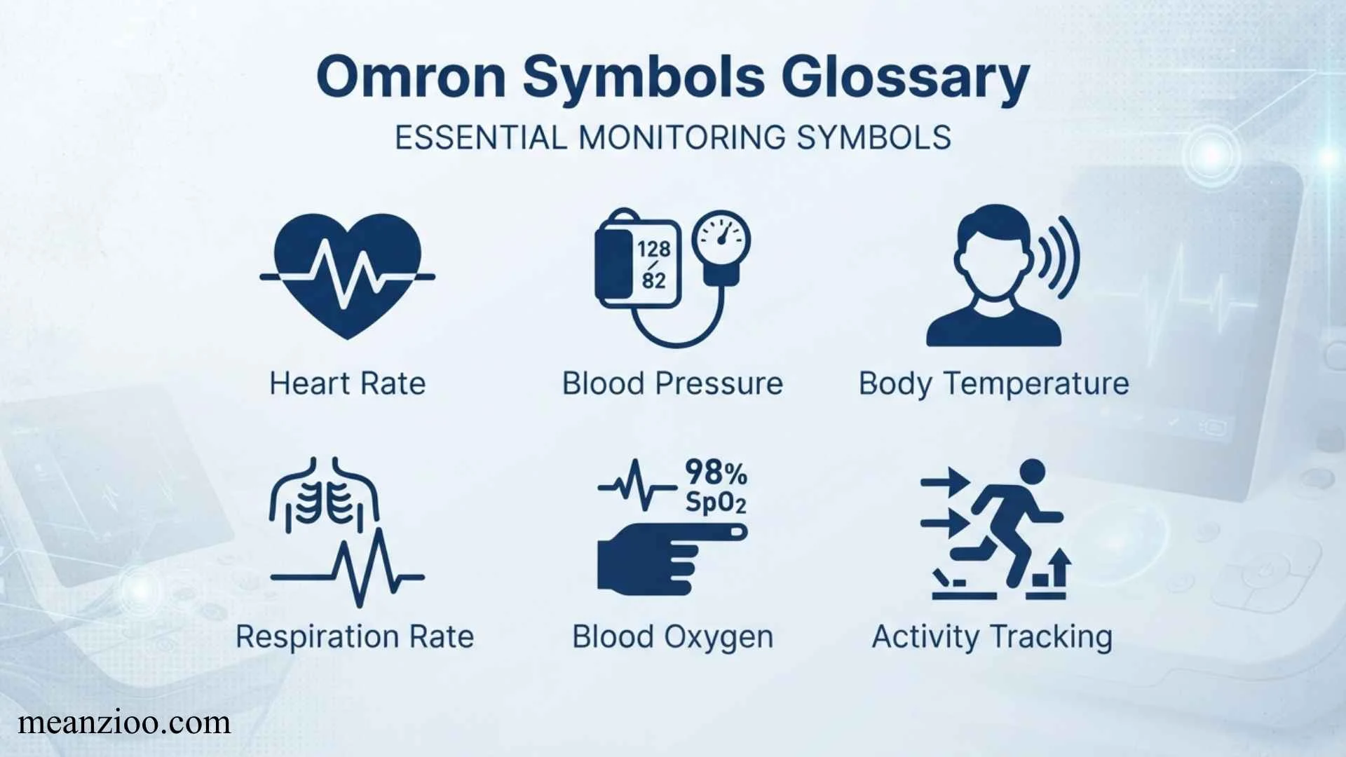
An Omron symbols glossary helps users understand the icons, abbreviations, labels, and symbols commonly found on Omron products, manuals, control systems, and technical documentation.
Because Omron manufactures equipment across automation, sensing, control, safety, healthcare, and other categories, the meaning of a symbol depends on the specific product and documentation.
This guide explains common Omron symbols and their meanings, how to interpret symbols on Omron industrial equipment, what common electrical and PLC-related abbreviations mean, and how to find the correct symbol information for a particular Omron product.
What Is an Omron Symbols Glossary?
An Omron symbols glossary is a reference for understanding symbols and technical markings associated with Omron equipment.
These symbols may appear on:
- PLCs
- HMIs
- Sensors
- Relays
- Timers
- Counters
- Safety devices
- Temperature controllers
- Industrial switches
- Power supplies
- Control components
- Medical and healthcare products
- Product labels
- Wiring diagrams
- Instruction manuals
- Software interfaces
Not every Omron symbol has a universal meaning across every product family. A symbol on an Omron PLC may represent an electrical or programming function, while a symbol on an Omron blood pressure monitor may communicate a health-related status.
For that reason, the safest approach is to interpret a symbol together with its product family, model number, manual, and applicable standard.
Why Understanding Omron Symbols Matters

Correctly interpreting technical symbols can help users install, operate, troubleshoot, and maintain equipment safely.
Faster Troubleshooting
Recognizing an indicator symbol can help identify whether a device is operating normally or reporting an error.
Easier Wiring
Electrical symbols and terminal markings help technicians understand how components should be connected.
Better PLC Programming
PLC symbols, addresses, instructions, and status indicators help programmers understand control logic.
Safer Equipment Operation
Warning and safety symbols can communicate hazards or required precautions before a user operates equipment.
Easier Manual Reading
A glossary can make technical documentation easier to understand, especially when several abbreviations appear on the same page.
Omron Symbols Glossary at a Glance
The following table provides a practical starting point. Exact meanings can vary by Omron product and manual.
| Symbol / Term | Common Meaning | Typical Context |
| ON | Device or function active | Controls, indicators |
| OFF | Device or function inactive | Controls, indicators |
| RUN | Equipment or program running | PLCs, controllers |
| STOP | Operation stopped | PLCs, machinery |
| ERR / ERROR | Error or fault condition | Controllers, PLCs |
| ALM / ALARM | Alarm condition | Controllers, sensors |
| PWR | Power | Electrical equipment |
| IN | Input | I/O and control systems |
| OUT | Output | I/O and control systems |
| COM | Common connection | Electrical terminals |
| NO | Normally open | Relays, switches |
| NC | Normally closed | Relays, switches |
| A / B | Terminal or channel designation | Relays, switches, wiring |
| DC | Direct current | Power and control |
| AC | Alternating current | Power and control |
| V | Voltage | Electrical specifications |
| A | Current | Electrical specifications |
| Hz | Frequency | Electrical specifications |
| PLC | Programmable logic controller | Industrial automation |
| I/O | Input/output | Automation |
| HMI | Human-machine interface | Automation |
| PE | Protective earth | Electrical wiring |
| FG | Frame/function ground | Industrial equipment |
| LED | Light-emitting diode | Status indicators |
These are general technical abbreviations rather than a single official Omron-wide symbol dictionary.
Omron Symbols Meaning A1
OMRON blood pressure monitor par A1 ka meaning model ke display aur manual par depend kar sakta hai, is liye sirf “A1” ko ek universal OMRON symbol samajhna theek nahi. OMRON ke different monitors mein display indicators alag ho sakte hain, aur kuch models mein letters ya numbers memory, error, measurement, ya display-reference labels ke taur par bhi use hote hain.
Agar A1 aapke monitor ki screen par measurement ke waqt nazar aa raha hai, to apne exact model number ka instruction manual check karna sab se accurate tareeqa hai. OMRON ke support resources model-specific manuals aur troubleshooting information provide karte hain.
Iske opposite, agar aap manual ke diagram mein “A1” dekh rahe hain, to ho sakta hai woh display symbol ka naam nahi balki illustration ka reference ho. Isliye screen par nazar aane wale actual icon ko identify karna zaroori hai.
Omron M2 Symbols Meaning
OMRON M2 ek upper-arm blood pressure monitor hai jo IntelliSense technology, irregular heartbeat detection, cuff wrap guidance aur memory functions provide karta hai. M2 ke display par blood pressure readings ke saath measurement-related indicators bhi aa sakte hain.
Common M2 indicators ko samajhne ka simple tareeqa yeh hai:
- SYS — systolic, yani upper blood pressure reading.
- DIA — diastolic, yani lower blood pressure reading.
- Pulse — heart rate/pulse reading.
- Heartbeat indicator — measurement ke dauran heartbeat detection ko show karta hai.
- Irregular heartbeat indicator — measurement ke waqt irregular rhythm detect hone par appear ho sakta hai.
- Cuff wrap indicator — cuff ki positioning ya wrapping se related information de sakta hai.
- Battery indicator — batteries low ya depleted hone ki warning de sakta hai.
- Memory indicator — stored readings ko identify karne ke liye use hota hai.
M2 ke different versions mein features aur symbols change ho sakte hain. For example, current OMRON M2 page M2 HEM-7143-E ko irregular heartbeat detection, cuff wrap guidance, 30-reading memory aur IntelliSense technology ke saath list karta hai.
Omron SYS DIA Symbol Meaning
OMRON monitor par SYS aur DIA blood pressure ke do main numbers ko identify karte hain.
SYS ka matlab systolic blood pressure hai. Yeh pressure ko represent karta hai jab heart blood pump karne ke liye contract karta hai.
DIA ka matlab diastolic blood pressure hai. Yeh pressure ko represent karta hai jab heartbeats ke darmiyan heart relax karta hai.
For example, agar monitor par:
SYS 120 mmHg
DIA 80 mmHg
likha hai, to 120 systolic reading aur 80 diastolic reading hai.
OMRON manuals display diagrams mein systolic aur diastolic readings ko separate indicators ke taur par identify karte hain.
Yaad rakhein ke SYS/DIA labels khud koi error symbol nahi hain. Yeh simply monitor ko batate hain ke screen par kaunsa blood pressure value display ho raha hai.
Irregular Heartbeat Symbol on Blood Pressure Monitor Omron
OMRON blood pressure monitor ka irregular heartbeat symbol tab appear ho sakta hai jab device measurement ke dauran heartbeat rhythm mein irregularity detect kare.
OMRON ke mutabiq, irregular heartbeat rhythm us waqt define ki jati hai jab detected rhythm average rhythm se 25% kam ya 25% zyada ho. Kuch models mein symbol tab display hota hai jab irregular rhythm measurement ke dauran do ya zyada times detect ho.
Is symbol ka appear hona apne aap mein kisi specific heart condition ka diagnosis nahi hai. Measurement technique, movement aur other factors bhi reading ko affect kar sakte hain. Agar symbol baar baar readings ke saath appear ho, OMRON apne manuals mein healthcare professional se consult karne ki recommendation deta hai.
OMRON Blood Pressure Monitor Symbols Two Arrows
OMRON monitors par two-arrow ya positioning-type indicators ka meaning model ke hisaab se different ho sakta hai. Wrist blood pressure monitors mein arrows ya positioning indicators aksar monitor ko heart ke correct level par rakhne mein help karte hain.
For example, OMRON wrist monitors ke advanced positioning systems mein heart ke comparison mein monitor agar zyada high ya low ho to indicator user ko correct position ki taraf guide kar sakta hai. Correct position par heart-related indicator show ho sakta hai.
Isliye two arrows ko automatically “high blood pressure” ya “irregular heartbeat” samajhna sahi nahi. Agar aapke monitor par specific two-arrow icon hai, to exact model number ke manual se us symbol ko verify karna best hai.
OMRON Irregular Heartbeat Symbol 2
Kuch OMRON blood pressure monitors irregular heartbeat ko number ke saath show karte hain. For example, irregular heartbeat symbol ke saath 2 display ho sakta hai.
Iska matlab kuch models mein measurement ke dauran 2 irregular heartbeats detect hona hota hai. OMRON ke documentation mein kuch monitors ke liye irregular heartbeat counter ka example diya gaya hai jahan symbol ke saath 2 ya 3 detected irregular beats indicate kiye ja sakte hain.
Yeh “2” blood pressure value nahi hota. Yeh irregular heartbeat detection ka count ho sakta hai.
Important point: exact behavior model ke mutabiq change ho sakta hai. Agar aapka monitor irregular heartbeat symbol repeatedly show karta hai, readings ko carefully repeat karein aur persistent result ki surat mein healthcare professional se discuss karein.
Omron Symbols Glossary Wrist
OMRON wrist blood pressure monitors mein multiple symbols measurement ko samajhne mein help karte hain. Common indicators mein systolic reading, diastolic reading, heartbeat, cuff wrap guide, irregular heartbeat, battery aur deflation indicators shamil ho sakte hain.
Wrist monitors mein cuff positioning particularly important hai. OMRON ke kuch wrist models positioning guidance dete hain taake monitor heart ke level ke qareeb rahe. Correct positioning accurate measurement ke liye important hai.
Agar wrist monitor par cuff-wrap symbol warning de raha ho, cuff ko dobara correctly position karke measurement repeat karna chahiye. Movement error bhi measurement ko affect kar sakta hai.
Pressure Omron Symbols Glossary
OMRON blood pressure monitors par symbols ka basic glossary samajhne se screen par aane wali information ko read karna easy ho jata hai.
SYS: Systolic blood pressure.
DIA: Diastolic blood pressure.
Pulse: Heart rate measured during the reading.
Heartbeat icon: Measurement ke waqt heartbeat detection ko indicate karta hai.
Irregular heartbeat icon: Irregular rhythm detect hone ka indicator.
Battery icon: Battery status ke baare mein information.
Cuff wrap guide: Cuff ki correct ya incorrect positioning se related indicator.
Movement error: Measurement ke waqt body movement detect hone ka warning indicator.
Memory: Previously stored readings ko access karne se related indicator.
Deflation: Cuff se air release hone ke process ko indicate kar sakta hai.
OMRON ka official Symbols Glossary bhi IP ratings, cuff positioning, artery marks aur doosre equipment symbols ko explain karta hai.
Omron IntelliSense Symbols
OMRON IntelliSense ek technology hai jo blood pressure measurement ke dauran cuff inflation ko control karne ke liye use hoti hai. Iska purpose unnecessary over-inflation ko reduce karna aur measurement ko comfortable banana hai.
IntelliSense ko samajhte waqt ek important distinction hai: IntelliSense khud zaroori nahi ke display par ek single warning icon ho. Yeh monitor ki measurement technology ka naam hai.
OMRON M2 jaise models IntelliSense technology ke saath available hain. OMRON ke product information ke mutabiq, system cuff ko required level tak inflate karne mein help karta hai instead of unnecessarily over-inflating it.
Agar aapke monitor par IntelliSense naam ya related reference diya gaya hai, to iska connection usually monitor ke automatic inflation/measurement system se hota hai.
Omron Icons Meaning
OMRON blood pressure monitor ke icons ka meaning model ke mutabiq change ho sakta hai, lekin commonly screen par measurement, cuff, heartbeat, battery aur memory se related indicators milte hain.
Sabse important icons mein:
- Heart/heartbeat icon: Measurement ke waqt heartbeat detect hone ko indicate karta hai.
- Irregular heartbeat icon: Irregular rhythm detection ko indicate karta hai.
- Cuff icon: Cuff wrapping ya positioning se related information de sakta hai.
- Battery icon: Low ya depleted battery status.
- Movement icon: Measurement ke waqt movement detect hone par warning.
- Memory icon: Stored reading access karne ke liye.
- Deflation icon: Cuff pressure release hone ko show kar sakta hai.
- Positioning indicator: Kuch wrist models mein monitor ko heart ke correct level par rakhne mein help karta hai.
OMRON ka official Symbols Glossary bhi device symbols ko standard meanings ke saath explain karta hai.
Omron IP20 Symbols
IP20 ek blood-pressure reading ya medical warning symbol nahi hai. Yeh device ki Ingress Protection rating hai.
OMRON ke official Symbols Glossary ke mutabiq, IP20 ka matlab hai ke enclosure 12.5 mm se bade solid objects ke against protected hai, lekin liquid/water ke against protection provide nahi karta.
Iska practical meaning yeh hai ke IP20-rated equipment ko water, splashes aur moisture se protect karna important hai. IP20 mein:
- First digit 2: Certain larger solid objects/finger-sized access ke against protection.
- Second digit 0: Water protection nahi.
Isliye IP20 ko blood pressure result, heart rhythm warning, ya battery indicator ke saath confuse nahi karna chahiye. Yeh device enclosure ki protection classification hai.
IntelliSense Omron Symbols
IntelliSense OMRON ki automatic blood pressure measurement technology hai, jabke monitor par nazar aane wale symbols alag functions ko represent kar sakte hain.
OMRON M2 information ke mutabiq, IntelliSense technology cuff ko measurement ke liye inflate karti hai aur unnecessary over-inflation ko prevent karne mein help karti hai. M2 mein irregular heartbeat detection aur cuff wrap guidance bhi available hai.
Isliye agar aap “IntelliSense symbol” search kar rahe hain, to do cheezon ko separate rakhna useful hai:
Common Omron Status Symbols and Indicators
Many Omron industrial devices use LEDs or display indicators to communicate operating status.
PWR or Power Indicator
A PWR or power indicator generally shows that electrical power is being supplied to the device.
Depending on the product, the indicator may have different states or colors.
Always consult the model-specific manual before assuming that a particular LED color means a specific condition.
RUN Indicator
A RUN indicator commonly relates to normal operation or execution.
On a PLC or controller, it may indicate that the control program or system is running.
ERR or Error Indicator
An ERR or error indicator generally signals an abnormal condition.
Possible causes depend on the device and can include:
- Hardware problems
- Configuration errors
- Communication problems
- Programming errors
- Power-related issues
- Sensor or I/O faults
The indicator alone does not identify the exact cause. The product’s troubleshooting documentation should be checked.
ALM or Alarm Indicator
An ALM indicator commonly represents an alarm condition.
The exact alarm can vary significantly between product families.
Omron Electrical Symbols and Abbreviations
Omron control components use many standard electrical abbreviations.
Understanding these terms is useful when reading wiring diagrams.
NO — Normally Open
NO means normally open.
A normally open contact does not conduct in its normal, unactivated state. When the associated device operates, the contact can close.
NO contacts are common in:
- Push buttons
- Relays
- Limit switches
- Control circuits
NC — Normally Closed
NC means normally closed.
A normally closed contact conducts in its normal state and opens when actuated.
NC contacts are commonly used in:
- Stop circuits
- Safety circuits
- Limit switches
- Relays
COM — Common
COM usually means common terminal or common connection.
Its exact electrical function depends on the component.
A COM terminal may be associated with:
- Relay contacts
- Input circuits
- Output circuits
- Switching circuits
Never assume that all COM terminals have the same electrical potential.
DC — Direct Current
DC means direct current.
It is commonly used in control systems and industrial electronics.
Typical control voltages can include 24 V DC, but the correct voltage must always be taken from the product’s specifications.
AC — Alternating Current
AC means alternating current.
It is used in many power and control applications.
The allowable voltage and frequency depend on the specific Omron device.
PE — Protective Earth
PE generally identifies a protective-earth connection.
It is an important electrical safety connection and should be wired according to the equipment documentation and applicable electrical regulations.
FG — Frame Ground or Functional Ground
FG can refer to a frame or functional ground connection depending on the product.
Its exact purpose must be confirmed using the relevant wiring diagram because grounding terminology can differ between devices.
Omron PLC Symbols and Terms
Omron offers programmable logic controllers and related automation equipment. PLC documentation contains its own terminology and symbols.
PLC
PLC stands for Programmable Logic Controller.
A PLC receives inputs, executes a control program, and controls outputs.
A simplified system can be represented as:
Inputs → PLC → Program Logic → Outputs
I/O
I/O means Input/Output.
Inputs allow a controller to receive information from devices such as:
- Push buttons
- Sensors
- Switches
- Encoders
Outputs can control:
- Relays
- Motors
- Solenoid valves
- Lamps
- Other control devices
Input Symbols
An input represents information received by the PLC or control system.
Examples include:
- Start button
- Stop button
- Proximity sensor
- Photoelectric sensor
- Limit switch
Output Symbols
An output represents a signal produced by the controller.
Examples include:
- Motor command
- Solenoid activation
- Indicator lamp
- Relay output
Also Check This Post: Persian Symbols: Meanings, History, Origins, and Cultural Significance
Omron PLC Address Symbols
PLC programming often uses addresses to identify inputs, outputs, memory areas, and other data.
The exact address notation depends on the Omron PLC family and programming environment.
For example, Omron systems can use different memory-area conventions depending on the controller.
Common concepts include:
- Input areas
- Output areas
- Work areas
- Holding areas
- Timer areas
- Counter areas
- Data memory
Because address assignments are model- and software-dependent, users should consult the programming manual for the specific PLC rather than applying a generic address table to every Omron controller.
Omron Timer and Counter Symbols
Timers and counters are common concepts in PLC programming.
Timer
A timer allows a control program to respond based on elapsed time.
A simplified example is:
Input ON → Timer starts → Preset time reached → Output activates
Counter
A counter tracks events or pulses.
For example:
Sensor detects product → Counter increases → Preset count reached → Output activates
Timer and counter instructions can vary between Omron PLC generations and programming platforms, so the exact instruction name and symbol should be verified in the appropriate Omron documentation.
Omron Sensor Symbols
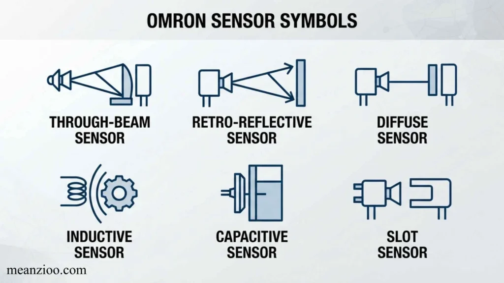
Omron manufactures many types of industrial sensors.
Common sensor categories include:
- Photoelectric sensors
- Proximity sensors
- Fiber-optic sensors
- Vision sensors
- Measurement sensors
- Safety sensors
- Encoders
Photoelectric Sensor
A photoelectric sensor detects objects using light.
A simplified concept is:
Emitter → Light beam → Object → Receiver
The actual sensor symbol used in a schematic depends on the diagramming convention.
Proximity Sensor
A proximity sensor detects an object without requiring physical contact.
Inductive proximity sensors are commonly used to detect metal objects.
Safety Sensor
Safety sensors are designed for machine safeguarding applications.
Examples include safety light curtains and other protective sensing systems.
Because safety equipment is involved, the symbol, wiring, and operating requirements should always be interpreted using the exact product documentation.
Omron Relay Symbols
Relays use electrical symbols to show their coils and contacts.
A basic relay may contain:
- Coil
- Normally open contact
- Normally closed contact
- Common connection
The relay coil controls the state of its associated contacts.
Relay Coil
The coil represents the electromagnetic component that operates the relay.
Relay Contacts
Relay contacts can be:
- Normally open
- Normally closed
- Changeover contacts
The exact schematic symbol depends on the relay configuration and the applicable drawing standard.
Omron Switch Symbols
Omron manufactures many types of switches and control devices.
Common examples include:
- Push buttons
- Selector switches
- Limit switches
- Rotary switches
- Rocker switches
- DIP switches
- Tactile switches
Push Button Symbols
A push button may be represented as either normally open or normally closed depending on its contact arrangement.
Limit Switch Symbols
Limit switches detect mechanical movement or position.
They can be used to determine whether:
- A door is closed
- A machine has reached a position
- A mechanism has reached its travel limit
The physical appearance and schematic symbol should not be confused. The product itself may look different from the electrical symbol used in a circuit diagram.
Omron HMI Symbols
An HMI, or Human-Machine Interface, allows operators to interact with an industrial control system.
HMI screens can contain symbols representing:
- Motors
- Valves
- Pumps
- Sensors
- Alarms
- Production status
- Temperature
- Pressure
- Flow
- Machine states
These graphical elements are often configured by the system designer rather than representing a single universal Omron symbol.
Alarm Symbols
Alarm icons generally communicate that a monitored condition requires attention.
Status Symbols
Status graphics can indicate conditions such as:
- Running
- Stopped
- Ready
- Faulted
- Manual mode
- Automatic mode
The exact meaning should be defined by the HMI application and its documentation.
Omron Safety Symbols
Safety symbols deserve particular attention because they may indicate hazards, mandatory actions, or important precautions.
Common safety concepts include:
- Warning
- Caution
- Electrical hazard
- Protective earth
- Read the manual
- Emergency stop
- Safety-related functions
Warning Symbols
A warning generally indicates a condition that could result in injury or damage if instructions are ignored.
Caution Symbols
A caution generally draws attention to conditions requiring careful handling or operation.
The exact meanings and severity classifications should be taken from the product’s official documentation rather than inferred from the icon alone.
Omron Medical Device Symbols
Omron also produces healthcare products, including home blood pressure monitors and other medical devices.
These products can use symbols that differ from industrial automation terminology.
Examples may relate to:
- Battery status
- Cuff positioning
- Measurement status
- Memory
- Irregular heartbeat detection
- User profiles
- Date and time
- Bluetooth or connectivity
Because these symbols can relate to health measurements, the specific product manual should always take priority over a general symbol glossary.
Omron Blood Pressure Monitor Symbols
Blood pressure monitors can display several indicators during or after a measurement.
Depending on the model, users may encounter symbols associated with:
- Blood pressure readings
- Pulse
- Cuff placement
- Irregular heartbeat
- Body movement
- Memory
- Battery
- Connection status
Why Model-Specific Information Matters
Different Omron blood pressure monitors do not necessarily use exactly the same display icons.
Therefore, if you are trying to identify a symbol on an Omron healthcare product, use the model number to locate the correct instruction manual.
A general glossary should be treated as a starting point, not a substitute for the product-specific manual.
Omron Symbol Colors and LED Indicators
Users sometimes search specifically for the meaning of Omron red, green, orange, or other indicator lights.
The important point is that LED color does not have one universal meaning across every Omron product.
For example, an indicator color may represent:
- Normal operation
- Warning
- Error
- Communication
- Power
- Sensor detection
- A specific machine state
The same color can have different meanings on different product families.
Therefore:
Do not diagnose a device solely from LED color.
Check the model-specific manual and indicator table.
How to Read an Omron Wiring Diagram
Reading an Omron wiring diagram becomes easier when you understand the basic sequence.
Step 1: Identify the Product
Find the exact model number.
Step 2: Identify the Power Supply
Determine whether the device uses:
- AC
- DC
- A particular voltage range
Step 3: Find the Terminals
Look for labels such as:
- Power
- COM
- Input
- Output
- Ground
- Communication
Step 4: Identify Input and Output Connections
Determine which terminals receive signals and which terminals provide signals.
Step 5: Check Contact Types
Identify whether contacts are:
- NO
- NC
- Changeover
Step 6: Check the Wiring Diagram
Compare the physical terminals with the official schematic.
Never rely solely on a generic diagram if the device is connected to live electrical equipment.
Also Check This Post: Satanic Hand Symbols: Meanings, Origins & What They Really Represent
Omron Symbols vs. Standard Electrical Symbols
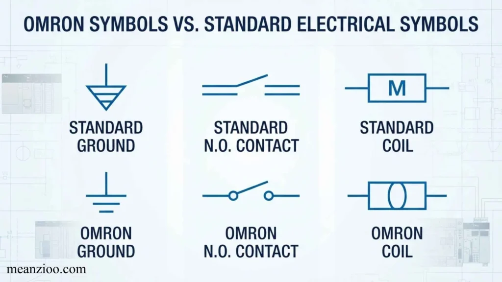
An important distinction is that many symbols appearing in Omron documentation are not proprietary symbols.
They may be based on established electrical, electronic, automation, or engineering conventions.
For example:
- NO = normally open
- NC = normally closed
- AC = alternating current
- DC = direct current
- PE = protective earth
These are widely used technical conventions.
Other symbols may be specific to:
- An Omron product
- A particular PLC family
- An Omron software environment
- A particular HMI application
- A particular medical device
This is why a model number is often essential when identifying an unfamiliar symbol.
Common Mistakes When Interpreting Omron Symbols
Assuming Every Omron Symbol Is Universal
Omron has many product categories, so symbols can vary considerably.
Ignoring the Model Number
The model number is often the fastest way to find the correct manual.
Treating an LED Color as Universal
An orange or red indicator does not necessarily mean the same thing on every device.
Confusing Physical Icons With Schematic Symbols
The icon printed on a product may not be the same as the electrical symbol used in a circuit diagram.
Guessing Terminal Functions
Never assume that similarly named terminals have identical functions across different products.
Using an Old Manual for a New Model
Product revisions can change specifications, terminal layouts, and indicator meanings.
Ignoring Safety Instructions
Electrical and industrial equipment should be installed and serviced according to the manufacturer’s instructions and applicable regulations.
How to Find the Meaning of an Unknown Omron Symbol
If you encounter a symbol you do not recognize, use a systematic approach.
1. Find the Model Number
Look for the complete product or series number on the device.
2. Identify the Product Category
Determine whether it is:
- PLC
- Sensor
- Relay
- Switch
- Controller
- HMI
- Safety device
- Healthcare product
3. Locate the Official Manual
Use Omron’s official documentation for the exact model.
4. Search the Manual for the Symbol
Look at sections such as:
- Indicator meanings
- Terminal descriptions
- Wiring
- Specifications
- Error messages
- Display symbols
- Safety precautions
5. Compare the Symbol With the Diagram
Make sure the symbol is being interpreted in the correct context.
Omron Symbols Glossary: Quick Reference
| Abbreviation | Meaning | Common Use |
| AC | Alternating current | Power |
| DC | Direct current | Power/control |
| COM | Common | Terminals |
| ERR | Error | Status |
| ALM | Alarm | Status |
| PWR | Power | Status |
| RUN | Running | PLC/control |
| STOP | Stopped | PLC/control |
| IN | Input | I/O |
| OUT | Output | I/O |
| NO | Normally open | Contacts |
| NC | Normally closed | Contacts |
| PLC | Programmable logic controller | Automation |
| I/O | Input/output | Automation |
| HMI | Human-machine interface | Operator control |
| PE | Protective earth | Electrical safety |
| FG | Frame/function ground | Grounding |
| V | Volt | Voltage |
| A | Ampere | Current |
| Hz | Hertz | Frequency |
| LED | Light-emitting diode | Indicators |
Frequently Asked Questions About Omron Symbols
What does the RUN symbol mean on an Omron PLC?
RUN generally indicates that the PLC or control system is in a running or operating state. The exact indicator behavior depends on the specific PLC model.
What does ERR mean on an Omron device?
ERR generally indicates an error or abnormal condition. The exact cause must be determined from the device’s indicator table, error code, or troubleshooting documentation.
What does ALM mean on an Omron controller?
ALM generally means alarm and indicates that an alarm condition has occurred. The specific condition depends on the controller and its configuration.
What does PWR mean on an Omron device?
PWR usually means power and indicates the status of the device’s power supply.
What do NO and NC mean on an Omron relay?
NO means normally open, while NC means normally closed. They describe the contact state when the relay is in its normal, non-energized condition.
What does COM mean on an Omron relay?
COM generally means the common terminal associated with a contact set. Its exact electrical relationship should be confirmed from the relay’s wiring diagram.
What does I/O mean in Omron automation?
I/O means input/output. Inputs receive signals from field devices, while outputs send control signals to other devices.
What does PLC mean in Omron documentation?
PLC means Programmable Logic Controller, a type of industrial controller used to monitor inputs, execute programmed logic, and control outputs.
Why do Omron symbols differ between products?
Omron manufactures products across several industries and product categories. Some symbols follow standard electrical conventions, while others are specific to a particular product, software environment, or application.
How can I identify an unknown Omron symbol?
Find the exact model number, identify the product category, and consult the official instruction manual or technical documentation for that model.
Are Omron symbols standardized?
Some Omron symbols and abbreviations are based on widely recognized electrical and engineering conventions. Others are product-specific. Therefore, not every symbol should be assumed to have a universal meaning across all Omron equipment.
Conclusion
An Omron symbols glossary is useful for understanding the technical language found on Omron equipment and documentation, but there is no single symbol dictionary that applies identically to every Omron product.
Common terms such as PWR, RUN, ERR, ALM, COM, NO, NC, AC, DC, PLC, I/O, HMI, PE, and FG provide a useful foundation for reading industrial and electrical documentation.
At the same time, specialized symbols can differ between PLCs, sensors, relays, controllers, HMIs, safety products, and healthcare devices. The same indicator color or abbreviation may therefore have a different meaning depending on the product.
For the most accurate interpretation, identify the exact Omron model number and use its official documentation. This is particularly important for wiring, electrical connections, safety equipment, and medical devices.
A good glossary should help you understand the terminology, but the manufacturer’s model-specific manual should remain the final reference whenever a symbol affects installation, operation, troubleshooting, or safety.
:::
I can also create an image showing the most common Omron symbols, abbreviations, and their meanings as a visual glossary.
Also Check This Post: Samurai Symbols: Meanings, History, Famous Clan Crests, and Their Significance

I’m Ryan Mitchell, and I write about modern English, trending slang, and online expressions. I enjoy explaining the meanings, origins, and real-life usage of popular words in a simple way. I believe learning slang is an important step toward understanding today’s English-speaking culture. Through my work, I aim to help readers speak more naturally and stay updated with the latest language trends.
 Charlotte Hayes