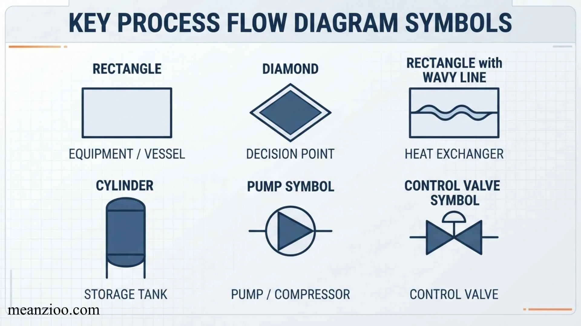
Process flow diagram symbols are standardized visual shapes used to represent activities, decisions, data, documents, inputs, outputs, and other elements within a process. By combining these symbols with connecting arrows, a complex workflow can be displayed as a clear sequence that is easier to understand, document, analyze, and improve.
Whether you are mapping a business workflow, manufacturing operation, software process, quality procedure, or administrative task, knowing the meaning of each process flow diagram symbol helps you create diagrams that other people can understand quickly.
This guide explains the most common process flow diagram symbols and their meanings, when to use each one, how they differ from ordinary flowchart symbols, relevant notation standards, common mistakes, and practical examples.
What Are Process Flow Diagram Symbols?
Process flow diagram symbols are graphical shapes used to visually describe the components and sequence of a process.
Instead of explaining a workflow entirely with paragraphs, a process diagram can show it visually:
Start → Receive Request → Review Information → Make Decision → Complete Process → End
Each stage is represented by an appropriate symbol.
For example:
- An oval commonly represents the start or end of a process.
- A rectangle represents an activity or process.
- A diamond represents a decision.
- A parallelogram represents input or output.
- A cylinder commonly represents stored data or a database.
- Arrows show the direction of flow.
The purpose is not simply to make a process look visual. The symbols create a consistent visual language that allows readers to understand what happens, when it happens, and what can happen next.
Why Are Process Flow Diagram Symbols Important?
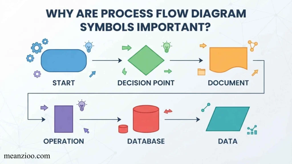
A process can contain dozens or hundreds of individual actions. Explaining every step in prose can make the procedure difficult to follow.
A process flow diagram simplifies that information.
Make Complex Processes Easier to Understand
A visual sequence lets readers see the relationship between activities instead of interpreting a long block of text.
Show Decisions and Alternative Paths
Decision symbols make branching points obvious.
For example:
Is the application complete?
- Yes → Continue review
- No → Request missing information
Identify Process Problems
Mapping a process can reveal:
- Duplicate activities
- Unnecessary approvals
- Repeated data entry
- Bottlenecks
- Excessive decision points
- Unclear responsibilities
- Unnecessary manual work
Improve Communication
A diagram gives teams a shared representation of how a process operates.
Support Training
New employees can use process diagrams to understand procedures without reading an entire operations manual.
Help With Process Improvement
Once the current workflow is visible, teams can identify steps that could be simplified, eliminated, automated, or reorganized.
Process Flow Diagram Symbols and Their Meanings
Different organizations and diagramming standards can use variations, but several symbols are widely recognized in traditional flowchart and process documentation.
The following chart provides a quick reference.
| Symbol | Common Shape | Meaning | Typical Example |
| Terminator | Oval / rounded rectangle | Start or end | Start Process |
| Process | Rectangle | Activity or task | Verify Order |
| Decision | Diamond | Decision or condition | Is Order Approved? |
| Flowline | Arrow | Direction of process | Next Step |
| Input/Output | Parallelogram | Data entering or leaving | Enter Customer Data |
| Document | Document shape | Document or report | Generate Invoice |
| Database | Cylinder | Stored data | Customer Database |
| Manual Input | Slanted-top shape | Human data entry | Enter Order Number |
| Manual Operation | Manual-operation shape | Manually performed task | Inspect Product |
| Predefined Process | Double-sided rectangle | Subprocess defined elsewhere | Run Payroll |
| Connector | Circle | Connects diagram sections | Connector A |
| Off-Page Connector | Pentagon-like shape | Flow continues elsewhere | Continue on Page 2 |
The exact appearance can vary depending on the software, notation system, or industry.
1. Terminator Symbol
The terminator symbol identifies where a process begins or ends.
It is traditionally shown as an oval or rounded rectangle.
Meaning
The terminator communicates an entry or exit point in a workflow.
Examples
- Start
- Begin application
- End
- Process complete
- Order completed
A simple diagram might begin with:
Start → Receive Application
and finish with:
Approve Application → End
When to Use It
Use a terminator whenever the reader needs to clearly identify the beginning or conclusion of the process.
2. Process Symbol
The process symbol is usually a rectangle.
It represents an action, operation, task, or activity performed as part of the workflow.
Examples
- Review application
- Verify payment
- Calculate total
- Package product
- Send invoice
- Inspect component
When to Use It
Use a process rectangle when something happens as part of the workflow.
For example:
Receive Order → Verify Order → Prepare Shipment
Each activity can be represented by a process rectangle.
Best Practice
Keep process descriptions short and action-oriented.
Instead of:
The customer information is checked by the employee
use:
Verify customer information
This makes the diagram easier to scan.
3. Decision Symbol
The decision symbol is traditionally represented by a diamond.
It indicates that the process needs to evaluate a question, condition, or choice.
Examples
- Is payment approved?
- Is inventory available?
- Is the application complete?
- Does the customer qualify?
- Is the product defective?
The decision normally creates two or more paths.
For example:
Is inventory available?
Yes → Prepare Order
No → Notify Customer
Best Practice for Decision Symbols
Write decisions as clear questions whenever possible.
Instead of:
Payment
use:
Is payment approved?
Then label the outgoing arrows clearly:
- Yes
- No
This prevents readers from guessing what each branch means.
Also Check This Post: Samurai Symbols: Meanings, History, Famous Clan Crests, and Their Significance
4. Flowline or Arrow Symbol
A flowline shows how the process moves from one symbol to another.
It is normally represented by a line ending in an arrow.
Meaning
The arrow communicates sequence and direction.
For example:
Start → Receive Request → Review Request → Approve Request → End
Why Flow Direction Matters
A diagram can contain all the correct shapes and still be difficult to understand if the arrows are poorly organized.
Choose a consistent direction, such as:
Top to bottom
or
Left to right
Avoid unnecessary line crossings whenever possible.
5. Input/Output Symbol
The input/output symbol is traditionally represented by a parallelogram.
It identifies information entering or leaving a process.
Input Examples
- Enter customer information
- Receive order details
- Scan barcode
- Enter product number
Output Examples
- Display results
- Print report
- Send confirmation
- Generate output
When to Use It
Use the input/output symbol when the distinction between an activity and the information being entered or produced is important.
For example:
Enter Customer Details → Validate Customer Details → Display Confirmation
6. Document Symbol
The document symbol represents a document that is used, generated, or processed.
It is typically drawn as a rectangle with a curved or wavy lower edge.
Examples
- Invoice
- Application
- Purchase order
- Inspection report
- Contract
- Delivery note
- Receipt
For example:
Review Order → Generate Invoice → Send Invoice
The document symbol makes it clear that the invoice is an actual document rather than simply another action.
7. Multiple Document Symbol
A multiple-document symbol represents several documents or a collection of documents.
It can be useful when a process creates or handles:
- Multiple invoices
- Several forms
- A set of reports
- Multiple copies
- A document package
For example:
Complete Application → Prepare Required Documents → Submit Package
If the collection of documents is important to the workflow, a multiple-document symbol can communicate this more clearly than several individual document symbols.
8. Database Symbol
A database symbol is commonly represented by a cylinder.
It indicates that information is stored in a database or structured data repository.
Examples
- Customer database
- Employee records
- Inventory system
- Order database
- Transaction database
A workflow might look like:
Enter Customer Data → Validate Data → Store Customer Record
The database symbol tells the reader that the information is being stored rather than merely displayed.
When to Use It
Use the database symbol when persistent electronic data storage is an important part of the process.
9. Data Storage Symbol
Data-storage symbols indicate that information is retained for later retrieval or processing.
Depending on the notation being used, different shapes can represent different storage mechanisms.
Examples include:
- Database
- File
- Data repository
- Temporary storage
- External storage
If your organization follows a specific notation standard, use its defined representation rather than mixing symbols from different systems.
10. Manual Input Symbol
The manual input symbol represents information entered manually by a person.
It is generally shown with a slanted top edge.
Examples
- Enter username
- Type customer number
- Enter order details
- Fill out an online form
- Manually enter inventory quantity
Why It Is Useful
This symbol distinguishes human data entry from information generated automatically by software or another system.
That distinction can be particularly useful when analyzing opportunities for automation.
11. Manual Operation Symbol
The manual-operation symbol represents an activity performed manually rather than automatically.
Examples
- Inspect product
- Sign document
- Manually count inventory
- Physically move materials
- Check equipment
This symbol is useful in manufacturing, logistics, administration, and other processes where some activities are automated and others depend on human action.
12. Predefined Process Symbol
A predefined process represents a procedure that is already defined elsewhere.
It is commonly drawn as a rectangle with additional vertical lines on both sides.
Example
A main workflow might show:
Receive Employee Request → Run Payroll Procedure → Review Result → End
Instead of placing every payroll step into the main diagram, the predefined-process symbol can point to a separate detailed payroll workflow.
Why Use It?
It helps prevent large diagrams from becoming overloaded with detail.
13. Connector Symbol
A connector links different parts of a flowchart without requiring a long line across the page.
It is commonly represented by a small circle.
When to Use Connectors
Connectors are helpful when:
- The diagram is large.
- Lines would cross.
- A process continues in another area.
- The same page contains several sections.
Use clear labels such as A, B, or another identifier so readers know where the flow continues.
14. Off-Page Connector
An off-page connector indicates that the workflow continues on another page or diagram.
This is particularly useful for large business, engineering, and operational processes.
For example:
Page 1 → Connector A
and:
Page 2 → Connector A → Continue Process
It allows the overall workflow to remain organized without drawing extremely long connecting lines.
Process Flow Diagram Symbols by Function
Another useful way to understand the symbols is to group them according to what they do.
Symbols That Represent Activities
These include:
- Process
- Manual operation
- Predefined process
They tell the reader what happens.
Symbols That Represent Decisions
The decision diamond tells the reader where the workflow can change direction.
Symbols That Represent Data
These include:
- Input/output
- Database
- Data storage
- Manual input
They tell the reader what information enters, leaves, or is stored.
Symbols That Represent Documents
Document symbols identify paperwork, reports, forms, invoices, and similar records.
Symbols That Represent Flow
Flowlines and connectors explain where the process goes next.
Symbols That Represent Boundaries
Terminators and off-page connectors help establish where the workflow begins, ends, or continues elsewhere.
Process Flow Diagram Symbols vs. Flowchart Symbols
The terms process flow diagram and flowchart are sometimes used interchangeably, but their meaning can vary by industry.
What Is a Flowchart?
A flowchart generally illustrates the logical sequence of a process using symbols connected by arrows.
It can represent:
- Business procedures
- Algorithms
- Administrative workflows
- Decision-making processes
- Troubleshooting procedures
What Is a Process Flow Diagram?
A process flow diagram can describe the movement of activities, information, materials, or operations through a process.
In manufacturing and engineering environments, the term may have a more specialized meaning than it does in general business documentation.
Therefore, always consider the industry and the notation standard being used.
Process Flow Diagram Standards and Notation
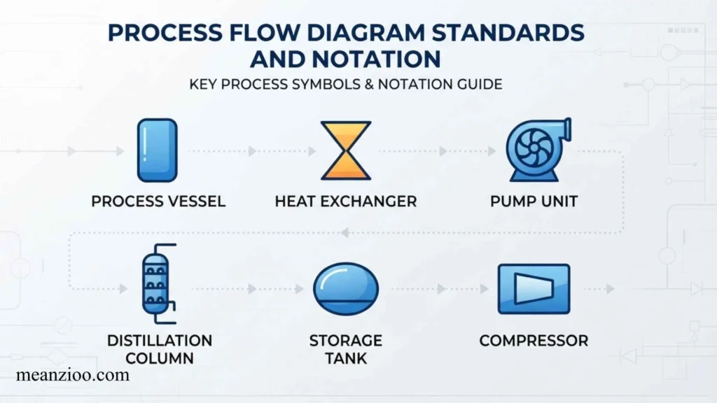
There is no single shape vocabulary that must be used identically for every diagram in every situation.
Different industries and standards define different conventions.
ISO 5807
ISO 5807 provides conventions for documentation symbols and conventions used for data, program, and system flowcharts, program network charts, and system resource charts.
When creating formal documentation, organizations may use ISO-based notation to maintain consistency.
ANSI-Style Flowchart Notation
Traditional American flowchart conventions have also influenced the symbols commonly seen in business and technical diagrams.
This is why shapes such as the rectangle for a process, diamond for a decision, and parallelogram for input/output are so widely recognized.
Why Standards Matter
Using a recognized notation can make diagrams easier to interpret across teams.
However, consistency is often more important than attempting to use every available symbol.
If a company has its own process-mapping standard, follow that standard throughout the documentation.
How to Create a Process Flow Diagram
Creating an effective diagram does not start with choosing shapes. It starts with understanding the process.
Step 1: Define the Process
First decide exactly what you are documenting.
For example:
Customer Order Fulfillment
Avoid trying to map an entire organization in one diagram.
Step 2: Define the Start and End
Determine what triggers the process and what event completes it.
Start: Customer submits order
End: Customer receives order
Step 3: List the Main Activities
Write down the major steps before creating the diagram.
For example:
- Receive order
- Verify order
- Check inventory
- Confirm payment
- Prepare shipment
- Ship order
- Update customer record
Step 4: Identify Decisions
Find points where the workflow can take different paths.
For example:
Is the product available?
- Yes → Prepare shipment
- No → Notify customer
Step 5: Identify Inputs and Outputs
Determine what information enters and leaves each stage.
Examples include:
- Customer information
- Order information
- Payment confirmation
- Shipping information
Step 6: Identify Documents and Data Storage
Determine whether the workflow creates documents or stores information.
Examples:
- Invoice
- Receipt
- Customer record
- Inventory database
Step 7: Select Symbols
Assign the appropriate symbol to each component.
Step 8: Connect the Symbols
Use arrows to establish the sequence.
Step 9: Review the Diagram
Ask someone unfamiliar with the process to follow the diagram.
If they cannot determine what happens next, the diagram may need clearer labels or a simpler structure.
Process Flow Diagram Example
Consider a basic customer order process.
Start
↓
Receive Order
↓
Check Inventory
↓
Is Product Available?
Yes → Confirm Payment → Prepare Shipment → Ship Order → Update Database → End
No → Notify Customer → End
This example uses several fundamental symbols:
- Terminator = Start and End
- Process = Receive Order, Confirm Payment, Prepare Shipment
- Decision = Is Product Available?
- Database = Update Database
- Flowline = Direction between steps
Also Check This Post: Infinity Symbols: ∞ ♾️ and More Symbols to Copy, Paste, Type, and Understand
Business Process Flow Diagram Example
A business approval workflow could look like this:
Start
↓
Employee Submits Request
↓
Manager Reviews Request
↓
Is Request Approved?
Yes → Finance Review
No → Return Request to Employee
↓
Is Budget Available?
Yes → Approve Purchase → Generate Purchase Order → End
No → Notify Employee → End
This type of workflow is useful for documenting approval procedures and identifying where requests are delayed.
Manufacturing Process Flow Diagram Example
A manufacturing workflow could contain:
Start
↓
Receive Raw Materials
↓
Inspect Materials
↓
Pass Inspection?
Yes → Begin Production
No → Reject or Return Materials
↓
Perform Quality Check
↓
Pass Quality Check?
Yes → Package Product → Store Product
No → Rework Product
This diagram makes inspection points and alternative paths easier to identify.
Software Process Flow Diagram Example
A simple login workflow could be represented as:
Start
↓
Enter Username and Password
↓
Validate Credentials
↓
Are Credentials Valid?
Yes → Create Session → Open Dashboard → End
No → Display Error → Try Again
This example shows how process flow symbols can be used to document software behavior as well as business processes.
Common Mistakes When Using Process Flow Diagram Symbols
A technically correct diagram can still be difficult to understand if the symbols are used poorly.
Using the Wrong Symbol for an Activity
An ordinary task should generally be represented by a process symbol.
Avoid choosing shapes simply because they look visually interesting.
Making Decision Symbols Vague
A diamond should represent a clear question or condition.
Instead of:
Customer
use:
Is customer information complete?
Putting Too Much Information in One Shape
A process box containing a paragraph of instructions can make a diagram difficult to read.
Keep labels concise and move detailed explanations into supporting documentation when necessary.
Creating Too Many Branches
A diagram with dozens of decision paths can become difficult to follow.
Consider dividing complex processes into subprocesses.
Crossing Arrows
Crossing flowlines can make the sequence ambiguous.
Reorganize the layout or use connectors where appropriate.
Mixing Notation Standards
Combining unrelated symbol conventions can confuse readers.
Choose a notation approach and apply it consistently.
Leaving Decisions Unlabeled
Decision branches should generally be labeled clearly.
For example:
Yes / No
or:
Approved / Rejected
Forgetting the Start or End
A reader should be able to determine where the documented process begins and finishes.
Best Practices for Designing Process Flow Diagrams
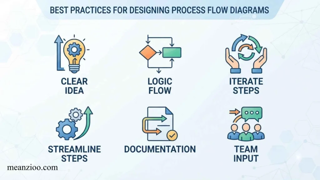
Keep the Main Flow Simple
Use a straightforward top-to-bottom or left-to-right structure whenever possible.
Use Consistent Symbol Sizes
Similar symbols should have consistent dimensions.
Keep Text Short
Use concise action phrases rather than paragraphs.
Label Decision Paths
Always make it clear which arrow corresponds to each outcome.
Avoid Unnecessary Symbols
You do not need a specialized symbol for every minor detail.
Use Subprocesses for Complex Workflows
If one process contains many steps, link it to a separate detailed diagram.
Make the Diagram Accessible
Use readable text, sufficient spacing, clear arrows, and labels that do not depend solely on color.
Process Flow Diagram Symbols in Different Industries
Business and Administration
Common applications include:
- Employee onboarding
- Purchase approvals
- Invoice processing
- Customer service
- Recruitment
- Document approval
Manufacturing
Manufacturers use process diagrams to document:
- Production
- Assembly
- Inspection
- Packaging
- Material handling
- Quality control
Software and IT
Common applications include:
- Authentication
- Data processing
- System workflows
- Troubleshooting
- API processes
- User interactions
Healthcare
Process diagrams can document:
- Patient registration
- Appointment scheduling
- Laboratory workflows
- Administrative procedures
- Patient discharge
Education
Schools and universities can map:
- Admissions
- Enrollment
- Course registration
- Examination procedures
- Student support
Process Flow Diagram Symbols Cheat Sheet
For quick reference, these are the symbols most readers should learn first:
| Symbol | Shape | Meaning |
| Terminator | Oval | Start or end |
| Process | Rectangle | Task or activity |
| Decision | Diamond | Condition or choice |
| Flowline | Arrow | Direction of flow |
| Input/Output | Parallelogram | Data input or output |
| Document | Wavy-bottom rectangle | Document |
| Database | Cylinder | Stored data |
| Manual Input | Slanted-top shape | Human data entry |
| Manual Operation | Specialized process shape | Manual activity |
| Predefined Process | Double-sided rectangle | Existing subprocess |
| Connector | Circle | Connects sections |
| Off-Page Connector | Pentagon-like shape | Continues on another page |
Frequently Asked Questions About Process Flow Diagram Symbols
What are the five basic process flow diagram symbols?
The five commonly recognized basic symbols are the terminator, process, decision, flowline, and input/output symbols. Together, they can represent the start and end of a workflow, activities, decisions, data movement, and process direction.
What does a rectangle mean in a process flow diagram?
A rectangle generally represents a process, activity, operation, or task.
What does a diamond mean in a process flow diagram?
A diamond represents a decision or condition that determines which path the workflow follows.
What does an oval mean in a process flow diagram?
An oval or rounded shape typically represents the start or end of a process.
What does a parallelogram mean in a process flow diagram?
A parallelogram traditionally represents input or output, such as entering information or producing results.
What does a cylinder mean in a process flow diagram?
A cylinder commonly represents a database or stored data.
What symbol represents a document?
A document is traditionally represented by a shape resembling a rectangle with a curved or wavy bottom edge.
What is the difference between a process and a decision symbol?
A process symbol represents something that happens, such as “Verify Order.” A decision symbol represents a question or condition, such as “Is Order Complete?”
What symbol shows the direction of a process?
A flowline or arrow shows the direction in which the workflow moves.
Do process flow diagram symbols have standard meanings?
Many traditional symbols have widely recognized meanings, but exact conventions can vary between standards, industries, and software applications. Formal projects should follow the notation standard specified by the organization or project.
What is the difference between a flowchart and a process flow diagram?
A flowchart generally illustrates the logical sequence of activities and decisions. A process flow diagram may be used more broadly to describe the movement of activities, information, materials, or operations through a process. The exact distinction depends on the industry and context.
Why are process flow diagrams useful?
They help people understand workflows, identify bottlenecks, document procedures, train employees, improve communication, and find opportunities to simplify or automate processes.
Conclusion
Understanding process flow diagram symbols is essential for creating diagrams that communicate processes clearly.
The most important symbols are the terminator for start and end points, rectangle for processes, diamond for decisions, arrow for flow direction, parallelogram for input and output, document symbol for documents, and cylinder for databases or stored data.
More specialized symbols—such as manual input, manual operation, predefined process, connectors, and off-page connectors—can be introduced when a workflow becomes more detailed.
The best process flow diagram is not necessarily the one containing the most symbols. It is the one that allows a reader to understand the process quickly and accurately.
Start by defining the workflow, identify its activities and decision points, choose consistent symbols, connect them with clear directional arrows, and keep complicated subprocesses separate when necessary.
When the right process flow diagram symbols and meanings are combined with a logical layout and concise labels, even complicated workflows can become easier to document, analyze, communicate, and improve.
Also Check This Post: Guatemala Symbols: National Symbols, Meanings, History, and Cultural Significance

Hi, I’m Charlotte Hayes. I love writing about the newest English slang, pop culture phrases, and digital communication. I spend my time exploring how language evolves across social media, gaming, and everyday conversations. I enjoy sharing easy-to-understand guides that help learners keep up with modern English. My goal is to make every article useful, accurate, and enjoyable for readers around the world.
Books:
- Everyday Slang Dictionary
- Fluent Through Informal English
 Ryan Mitchell