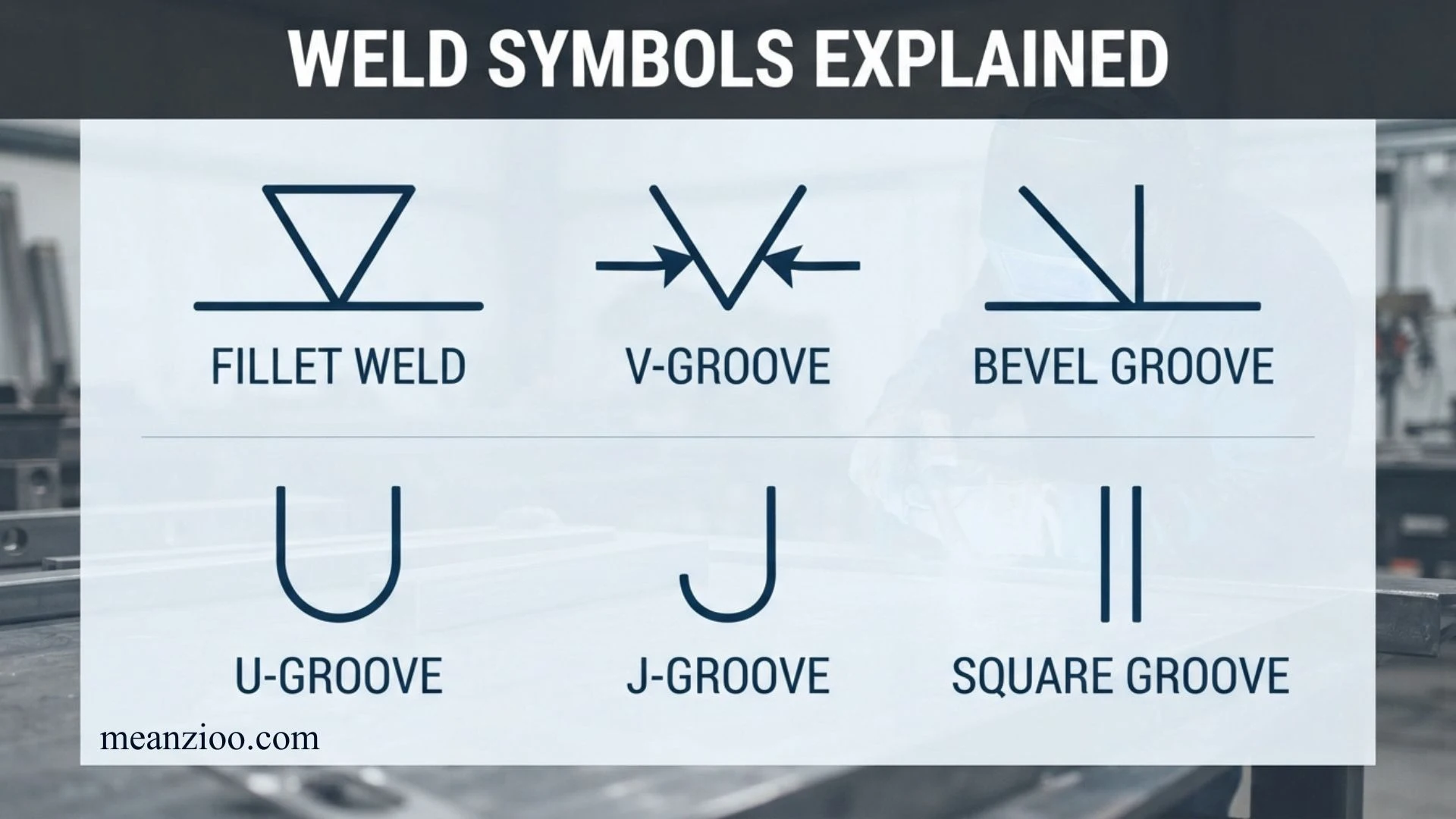
Weld symbols are a standardized visual language used on engineering drawings, fabrication blueprints, and manufacturing plans to communicate welding requirements. Instead of describing every weld in lengthy written instructions, a drawing can use a welding symbol to show the type of weld, location, size, length, spacing, finish, and other requirements.
For welders, welding inspectors, engineers, fabricators, designers, and students, knowing how to read weld symbols is an essential blueprint-reading skill. The most important references include AWS A2.4 for American welding-symbol practice and ISO 2553 for international applications. ISO 2553 defines symbolic representation of welded joints on technical drawings and covers information related to weld geometry, manufacture, quality, and testing.
This guide explains weld symbols from the basics to more advanced details, including common weld types, reference lines, arrows, dimensions, intermittent welds, supplementary symbols, AWS versus ISO conventions, common mistakes, and practical ways to interpret a welding drawing.
What Are Weld Symbols?
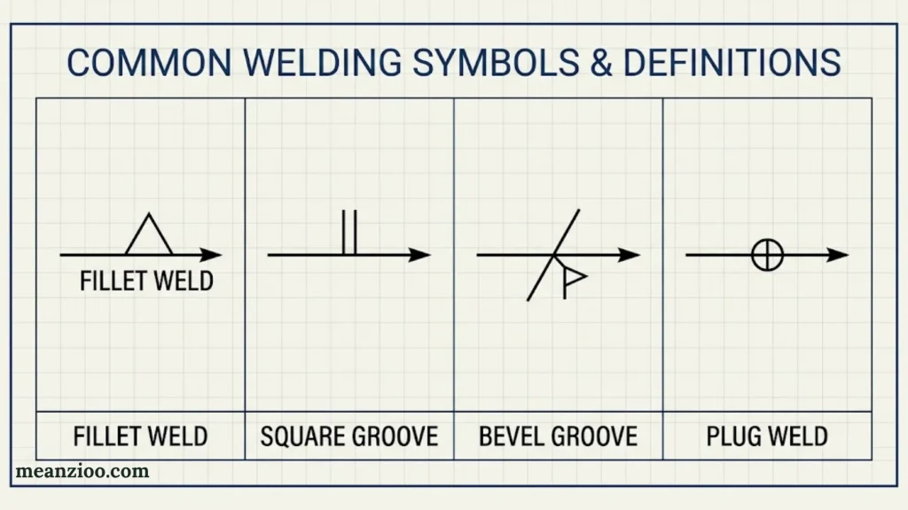
A weld symbol is a graphical representation used to identify a particular type of weld or joint preparation.
A welding symbol is the complete drawing notation. It can contain:
- Reference line
- Arrow
- Basic weld symbol
- Dimensions
- Supplementary symbols
- Tail
- Process or specification information
- Other notes required by the drawing
This distinction matters. A small triangle, for example, identifies a fillet weld, but the complete welding symbol can tell you where the fillet weld goes, how large it must be, how long it should be, whether it is intermittent, and what additional requirements apply.
AWS describes welding symbols as a communication system between the designer, welder, and inspector.
Why Are Welding Symbols Important?
Welding symbols allow technical drawings to communicate complicated fabrication requirements in a compact and standardized form.
Without welding symbols, a drawing might need a separate written instruction for every joint. A correctly prepared symbol can communicate the essential requirements directly on the drawing.
They are important because they help:
- Engineers specify joint requirements
- Welders understand fabrication instructions
- Inspectors determine what was specified
- Fabricators interpret blueprints
- Designers communicate joint preparation
- Manufacturing teams maintain consistency
- Students learn technical drawing conventions
- Quality-control personnel verify completed welds
A symbol is therefore more than a simple picture. It is an instruction that must be interpreted in the context of the applicable standard and drawing.
Butt Weld Symbol
A butt weld symbol identifies a weld used to join two components positioned in the same plane or nearly in the same plane. The edges of the components meet at a common joint, making this arrangement common in pipes, plates, structural frames, and pressure equipment.
A butt weld may use different edge preparations depending on material thickness, access, and strength requirements. The drawing specifies the required joint preparation through the appropriate groove or butt-weld symbol.
Common butt weld symbols and preparations include:
- Square butt weld: The edges remain square without a prepared groove.
- Single-V butt weld: Both edges are beveled to form a V-shaped groove.
- Single-bevel butt weld: One component has a beveled edge, while the other remains square.
- Double-V butt weld: The joint has V-shaped grooves on both sides.
- U-groove butt weld: Curved edges create a U-shaped groove.
- J-groove butt weld: One edge has a J-shaped preparation.
The symbol communicates the intended joint preparation, but the dimensions and additional notes determine the exact welding requirements.
For example, a single-V groove symbol may indicate that the welder must prepare the plate edges before welding. The drawing may also specify the groove angle, root opening, root face, weld size, or penetration requirements.
Important: Do not assume that every butt weld requires the same penetration. Follow the symbol dimensions, drawing notes, and applicable welding procedure.
AWS Welding Symbols
AWS welding symbols follow the American Welding Society’s standard for communicating welding and related inspection requirements on technical drawings. The main reference is AWS A2.4, which covers welding, brazing, and nondestructive examination symbols.
An AWS welding symbol combines several elements to communicate the designer’s instructions.
- Arrow: Identifies the joint or location where welding is required.
- Reference line: Provides the main line on which the weld symbol and related information appear.
- Basic weld symbol: Identifies the required weld type, such as a fillet or groove weld.
- Dimensions: Specify the required weld size, length, spacing, or other measurements.
- Tail: Provides space for additional information, such as a welding process, specification, or reference document.
- Supplementary symbols: Communicate requirements such as welding all around the joint or performing a field weld.
Under AWS conventions, the location of a weld symbol relative to the reference line identifies the side of the joint to be welded. A symbol below the reference line generally indicates the arrow side, while a symbol above it indicates the other side. Symbols on both sides can specify welding on both sides of the joint.
Common AWS weld symbols include:
- Fillet weld
- Square, V-groove, bevel-groove, U-groove, and J-groove welds
- Plug and slot welds
- Spot and seam welds
- Edge and surfacing welds
- Backing and back welds
Always check the drawing’s stated standard and edition. A familiar-looking symbol can carry different interpretation rules under another standard.
Fillet Weld Symbols Explained
A fillet weld symbol is represented by a right triangle. It indicates a weld used to join two surfaces that meet at an angle, commonly in T-joints, lap joints, and corner joints.
Fillet welds are widely used in steel fabrication because they can connect components without requiring the same type of edge preparation used for many groove welds.
To read a fillet weld symbol, pay attention to the triangle’s position and the dimensions around it.
- Triangle below the reference line: Indicates a fillet weld on the arrow side under AWS conventions.
- Triangle above the reference line: Indicates a fillet weld on the other side.
- Triangles on both sides: Indicate fillet welds on both sides of the joint.
- Number to the left: Commonly specifies the fillet weld size.
- Number to the right: Commonly specifies the weld length.
- Length and pitch information: Can indicate intermittent welds with separated weld segments.
For example, a fillet weld symbol with a size of 6 mm and a length of 50 mm may call for a 6 mm fillet weld extending 50 mm along the joint, provided the drawing uses metric dimensions and follows the applicable conventions.
The weld size is not the same as the weld length. The size describes the required cross-sectional dimension, while the length describes how far the weld extends along the joint.
Why it matters: An incorrectly interpreted fillet weld symbol can lead to undersized welds, unnecessary material use, distortion, or failure to meet design requirements. Always confirm the dimensions and whether the weld is continuous or intermittent.
AWS Weld Symbols Explained
Understanding AWS weld symbols becomes easier when you read the complete symbol instead of looking at the weld shape alone.
Start with the arrow and reference line. Identify the basic weld symbol, determine which side of the joint requires welding, and then read the dimensions and supplementary information.
Consider these common examples:
| Symbol feature | What it communicates |
| Fillet triangle | A fillet weld is required |
| V-shaped groove symbol | A V-groove weld is required |
| Rectangular plug-weld symbol | A plug weld is required |
| Circle at the arrow/reference-line junction | Weld all around the joint |
| Flag at the junction | Field weld, performed at the site rather than in the shop |
| Contour or finishing mark | Specifies the required weld surface profile or finishing method |
The symbol’s position, dimensions, and additional marks work together. A triangle alone identifies a fillet weld, but it does not tell you the required size, length, or whether the weld belongs on one side or both.
For example, a drawing might specify a fillet weld on both sides of a T-joint, with a particular size and length. Another drawing could use the same basic weld symbol but require welding around the entire joint.
These instructions are not interchangeable. The first defines the welds on both sides, while the second uses an all-around requirement when the symbol is applied appropriately.
When interpreting AWS drawings, remember these practical rules:
- Read all dimensions before preparing the joint.
- Check the reference-line position to identify the required side.
- Look for intermittent-weld length and pitch.
- Read the tail for process or specification references.
- Check finishing symbols and inspection notes.
- Never infer a missing weld dimension from the symbol shape alone.
ISO Weld Symbols Explained
ISO welding symbols are used internationally to communicate weld requirements on technical drawings. ISO 2553 defines how welds are represented, including their geometry, dimensions, quality requirements, and testing information.
One important difference between ISO and AWS drawings is the system used to identify the arrow side and the other side of the joint.
ISO 2553 recognizes two systems:
- System A: Uses a dual reference line consisting of a continuous line and a dashed line.
- System B: Uses a single reference line.
These systems must not be mixed within a drawing. The drawing should identify the applicable system and measurement units.
ISO welding symbols can specify a wide range of joint types and requirements, including:
- Fillet welds
- Square butt and groove welds
- Single-V and single-bevel welds
- U-groove and J-groove welds
- Intermittent welds
- Weld dimensions and spacing
- Weld surface contours and finishing
- Additional quality or inspection requirements
The symbol can also communicate whether welding is required on one side or both sides of a joint, depending on the selected system and symbol arrangement.
For example, a drawing prepared under ISO 2553 may use a fillet weld symbol with dimensions to specify the required weld size and length. However, the meaning and placement of those dimensions must be interpreted using the applicable ISO system rather than assumed from an AWS example.
Practical tip: When working with international suppliers or manufacturers, confirm whether the drawing follows ISO 2553 System A or System B before interpreting its weld symbols.
ANSI Weld Symbols Explained
ANSI welding symbols are often discussed in the context of American engineering drawings. However, the term can be misleading because welding symbols are governed by specific standards rather than by one universal symbol chart.
For many US engineering applications, AWS A2.4 is the key reference for standard welding symbols. ANSI may approve or adopt standards developed by other standards organizations, so the exact standard cited on the drawing matters more than the general label “ANSI welding symbols.”
When interpreting a drawing described as using ANSI welding symbols, check the title block, general notes, and applicable specifications first.
Pay particular attention to:
- The basic weld symbol and its position on the reference line
- Arrow-side and other-side requirements
- Weld size, length, and pitch
- Groove preparation and penetration details
- All-around and field-weld indicators
- Finishing requirements and supplementary notes
For instance, a triangle may identify a fillet weld, but you still need the dimensions to determine its required size. Similarly, a groove symbol identifies a type of weld preparation, but additional information may be necessary to define the joint fully.
If an older drawing refers to an ANSI standard, do not automatically replace its conventions with those of a newer standard. Confirm the contractual requirements and the version specified for the project.
SolidWorks Weld Symbols Explained
SolidWorks allows engineers and designers to add welding symbols to technical drawings so fabricators can understand how components should be joined. These annotations help communicate weld types, sizes, locations, and other manufacturing requirements.
The available options depend on the SolidWorks version, drawing environment, and annotation settings. Users should confirm that the symbols match the standard required for their project.
A typical workflow involves:
- Opening the engineering drawing.
- Selecting the appropriate annotation or weld-symbol command.
- Choosing the relevant weld type.
- Entering required dimensions and supplementary details.
- Placing the symbol and its arrow on the drawing.
- Reviewing the finished annotation against the design requirements.
SolidWorks drawings may include fillet weld symbols, groove weld symbols, all-around indicators, field-weld indicators, and other supported annotations.
For example, an engineer designing a welded steel bracket might use a fillet weld symbol to specify the connection between a bracket plate and its supporting component. The annotation can communicate the intended weld size and other requirements.
Before releasing the drawing, verify the following:
- The correct drafting standard is selected.
- Weld symbols are attached to the intended joints.
- Dimensions use the correct units.
- Arrow-side and other-side instructions are clear.
- Weld notes and supplementary requirements are complete.
- Exported PDF or drawing files preserve the symbols correctly.
A CAD annotation does not automatically guarantee that a weld is structurally adequate. Engineers must still determine the appropriate weld size, joint design, material requirements, and inspection criteria.
Basic Welding Symbols
Basic welding symbols identify the type of weld required on an engineering drawing. Each symbol represents a particular joint or welding arrangement, helping the welder understand the design without relying on lengthy written instructions.
The most common basic welding symbols include the following.
| Weld type | Typical symbol appearance | Purpose |
| Fillet weld | Right triangle | Joins surfaces that meet at an angle |
| Square-groove weld | Parallel straight edges | Joins components with square joint edges |
| V-groove weld | V shape | Identifies a joint prepared with a V-shaped groove |
| Bevel-groove weld | Single beveled side | Identifies a joint prepared with one beveled edge |
| U-groove weld | U shape | Identifies a rounded groove preparation |
| J-groove weld | J shape | Identifies a joint with a J-shaped preparation |
| Plug weld | Circular or hole-based joint representation | Joins overlapping components through a prepared hole |
| Slot weld | Elongated slot-based representation | Joins overlapping components through a slot |
| Spot weld | Circular symbol | Represents a localized spot weld |
| Seam weld | Seam-weld symbol | Represents a continuous or specified seam-welding arrangement |
| Edge weld | Edge-weld symbol | Identifies a weld along adjacent component edges |
| Surfacing weld | Surfacing symbol | Deposits weld metal on a surface to build up or restore material |
The exact graphic appearance and interpretation should be checked against the drawing’s governing standard.
A basic weld symbol identifies the weld type, but the complete welding symbol can communicate much more. It may include the required dimensions, the side to be welded, finishing instructions, and supplementary information.
For example, a V-groove symbol tells you the general groove type. The drawing may also need to specify the groove angle, root opening, and penetration requirements.
Remember: Never select a weld size or preparation based solely on a symbol chart. Use the complete drawing and approved welding procedure.
Weld Symbol Guide
A practical weld symbol guide helps you interpret engineering drawings in a consistent order. Instead of trying to memorize every symbol at once, learn the main components and then work through the information systematically.
How to read a welding symbol
- Find the arrow. Locate the joint or component that requires welding.
- Read the reference line. Identify where the weld symbol and its associated information appear.
- Identify the weld type. Look for a triangle, groove shape, or another basic symbol.
- Check the symbol’s position. Determine whether the arrow side, other side, or both sides require welding under the applicable standard.
- Read the dimensions. Check weld size, length, pitch, groove angle, and other measurements as applicable.
- Look for supplementary marks. Check for all-around welding, field welding, contour, or finishing requirements.
- Read the notes and title block. Confirm the applicable standard, units, welding process references, and project-specific instructions.
Example of a fillet weld callout
Imagine a drawing that specifies a 6 mm fillet weld with a 50 mm weld length.
- 6 mm identifies the specified weld size.
- 50 mm identifies the required weld length.
- The triangle identifies a fillet weld.
- The symbol’s position identifies the required side under the governing standard.
This example assumes that the drawing uses metric dimensions and that the size is defined according to its applicable convention.
The example does not automatically mean the weld must be repeated at 50 mm intervals. Intermittent welding requires the appropriate length and pitch information.
Common mistakes to avoid
- Confusing weld size with weld length.
- Assuming a weld symbol always applies to the arrow side.
- Missing a requirement to weld both sides.
- Treating an intermittent weld as continuous.
- Ignoring groove preparation or root-opening dimensions.
- Applying AWS interpretation rules to an ISO drawing without checking the system.
A consistent reading process reduces errors and helps welders produce joints that match the engineering design.
Types of Welding Symbols
Welding symbols are grouped by the type of weld, the location of the weld, and any additional manufacturing requirements. Learning these categories makes unfamiliar drawings easier to interpret.
Fillet weld symbols
These indicate welds commonly used in T-joints, lap joints, and corner joints. The symbol is a triangle, and its dimensions may specify weld size and length.
Groove weld symbols
Groove weld symbols indicate joints where the edges are prepared to receive weld metal. Common types include square, V, bevel, U, and J grooves.
The required preparation depends on factors such as material thickness, access, joint design, and the specified welding procedure.
Plug and slot weld symbols
Plug and slot welds join overlapping components through prepared openings. A plug weld typically uses a round hole, while a slot weld uses an elongated opening.
The drawing may specify the opening size, weld depth, spacing, or other relevant dimensions.
Spot and seam weld symbols
Spot welds form localized welded connections. Seam welds create a welded seam and are commonly associated with resistance-welding applications.
Their symbols may include dimensions or spacing requirements that define the intended arrangement.
Supplementary welding symbols
Additional marks provide instructions beyond the basic weld type. These may indicate:
- Welding all around a joint
- Welding at the job site
- A required weld contour
- A finishing method
- Backing or other supplementary requirements
Not every symbol describes a different weld process. Some symbols identify the geometry of the weld, while others provide instructions about its location or final appearance.
For accurate interpretation, read the complete callout rather than identifying only the central symbol.
Welding Symbol for Stitch Welding

A stitch weld, often called an intermittent weld, consists of separate weld segments placed along a joint rather than one continuous weld.
This arrangement is used when the design calls for welding at specified intervals. Depending on the application, intermittent welding can reduce the total weld length, limit heat input, and help manage distortion.
On welding drawings, stitch welding is commonly represented by an intermittent fillet weld symbol or another appropriate weld symbol with length and pitch dimensions.
Two measurements are particularly important:
- Weld length: The length of each individual weld segment.
- Pitch: The center-to-center distance between adjacent weld segments.
For example, a drawing might specify 25 mm weld segments at a 75 mm pitch. This means each weld segment is 25 mm long, with neighboring segments positioned 75 mm apart from center to center.
The unwelded gap between adjacent segments would be 50 mm in this example, assuming a regular pattern and the stated pitch convention.
Common stitch-welding patterns
- Intermittent weld on one side: Weld segments are placed on one side of the joint.
- Intermittent weld on both sides: Both sides of the joint receive specified weld segments.
- Chain intermittent weld: Segments on opposite sides align with one another.
- Staggered intermittent weld: Segments on opposite sides alternate positions.
Chain and staggered patterns must be identified according to the applicable welding standard and drawing conventions.
What to check before welding
- Confirm the length of each segment.
- Check the pitch and number of segments, if specified.
- Identify which side or sides require welding.
- Verify the required weld size.
- Check whether the drawing calls for chain or staggered placement.
- Follow the specified start and end locations.
Do not interpret stitch welding as permission to leave arbitrary gaps. The weld segments must follow the dimensions and placement requirements on the engineering drawing.
Welding Symbols UK
Welding symbols used in the United Kingdom commonly follow British and European standards, including BS EN ISO 2553 for the symbolic representation of welded joints.
These symbols help communicate weld geometry, dimensions, location, and additional requirements. They are used across engineering, construction, manufacturing, and fabrication.
When reading a UK welding drawing, check the following:
- Whether the drawing references BS EN ISO 2553 or another standard.
- Whether ISO System A or System B applies.
- Whether dimensions are in millimeters or another stated unit.
- Whether the drawing specifies weld size, length, pitch, or penetration.
- Whether additional notes define inspection, quality, or finishing requirements.
Common UK welding drawings include fillet weld symbols, butt and groove weld symbols, intermittent-weld callouts, and supplementary symbols for finishing or all-around welding.
Although some symbols look similar to those used in AWS drawings, their placement and dimensioning rules should not automatically be treated as identical.
For example, an engineer working with a UK supplier and a US fabrication shop should establish which standard governs the drawing. Both parties should use the same interpretation rules before fabrication begins.
The safest approach is to follow the standard stated in the drawing notes and confirm any unclear requirements with the design engineer.
British Welding Symbols
British welding symbols are used to communicate welding instructions on technical drawings prepared for UK projects. Modern British practice frequently relies on BS EN ISO standards, including BS EN ISO 2553.
Older drawings may reference earlier British Standards or project-specific conventions. Therefore, the drawing’s stated standard and revision remain important.
British welding symbols can communicate:
- Weld type and joint preparation
- Arrow-side and other-side requirements
- Weld dimensions and spacing
- Intermittent welding patterns
- Surface contour and finishing
- Additional quality and inspection information
British welding symbol examples
A fillet weld symbol identifies a fillet weld between intersecting surfaces. A V-groove symbol indicates a V-shaped groove preparation, while an intermittent-weld callout specifies separate weld segments and their spacing.
However, the shape alone does not provide every necessary instruction. The dimensions and supplementary details define the actual requirements.
When working with British welding symbols, avoid relying entirely on an American welding-symbol chart. Even when two symbols appear similar, their placement and dimensioning conventions may differ.
Best practice: Confirm the drawing standard, check the symbol’s position, read all dimensions, and consult the applicable standard when a requirement is unclear.
Plug Weld Symbol Example
A plug weld symbol identifies a weld used to join two overlapping components through a prepared round hole in one component. Weld metal fills the hole and bonds the component to the material underneath.
Plug welds are often used in sheet-metal fabrication, machinery, and structural applications where an overlapping joint is required.
How to read a plug weld symbol
A plug weld symbol communicates the required type of weld. Additional dimensions and notes specify how the weld should be made.
Look for the following information:
- Plug weld symbol: Identifies the required weld type.
- Hole diameter: Specifies the size of the prepared opening when required.
- Weld depth or filling requirements: Indicates how much of the hole must be filled, where applicable.
- Spacing: Defines the distance between plug welds when multiple holes are required.
- Countersink information: Specifies countersink requirements when applicable.
Plug weld example
Imagine two overlapping steel plates that must be joined using several plug welds. The drawing may specify a particular hole diameter and a center-to-center spacing between holes.
The welder prepares the openings and fills them according to the specified welding procedure. The welds connect the overlapping components without requiring a continuous weld along the entire joint.
A plug weld differs from a spot weld. A plug weld uses a prepared hole filled with weld metal, while a resistance spot weld creates a localized joint through a different welding process.
Important: Do not assume that a plug weld symbol automatically specifies a fully filled hole, a particular penetration depth, or a specific hole spacing. Follow the dimensions and notes provided on the drawing.
Understanding Weld Symbols
Understanding weld symbols requires more than memorizing individual shapes. You must interpret the symbol’s position, dimensions, and supplementary instructions together.
A complete welding symbol can communicate several requirements in a compact format. Learning how these elements work together helps prevent mistakes during fabrication and inspection.
The main parts of a welding symbol
Arrow line: Points toward the joint or component that requires welding.
Reference line: Carries the basic weld symbol and associated dimensions.
Tail: Provides space for additional information, such as welding process specifications or references to other documents. Its use depends on the applicable standard.
Basic weld symbol: Identifies the type of weld, such as a fillet, groove, plug, or slot weld.
Dimensions: Define requirements such as weld size, length, spacing, groove angle, or other relevant measurements.
Supplementary symbols: Add instructions about matters such as all-around welding, field welding, or weld contour.
Read the symbol in context
Consider a drawing that shows a fillet weld symbol with a specified size and length. The triangle identifies the weld type, while the dimensions define the required geometry and extent.
Now imagine that the drawing also includes an all-around symbol. This adds an instruction to weld around the joint’s perimeter, where applicable, rather than interpreting the callout as a weld along only one short section.
The symbol’s meaning depends on the entire callout and the governing standard.
Why weld-symbol interpretation matters
Correct interpretation helps you:
- Produce welds that meet the design requirements.
- Avoid unnecessary welding and material costs.
- Reduce defects caused by incorrect preparation or sizing.
- Understand the difference between continuous and intermittent welds.
- Communicate effectively with engineers, welders, and inspectors.
- Check completed work against the engineering drawing.
If a drawing contains conflicting dimensions, missing details, or unclear symbols, ask the responsible engineer for clarification before proceeding.
Basic Weld Symbols
Basic weld symbols represent the principal types of welds used in engineering drawings. They provide a standardized way to communicate joining requirements across fabrication and manufacturing projects.
The most useful symbols to recognize first are the fillet, groove, plug, slot, spot, seam, edge, and surfacing weld symbols.
| Basic weld symbol category | What it tells you |
| Fillet | A weld is required where surfaces meet at an angle |
| Groove | A joint requires a specified groove or edge preparation |
| Plug | A prepared hole is used to join overlapping components |
| Slot | An elongated opening is used for a welded connection |
| Spot | A localized spot-welding connection is required |
| Seam | A seam-welding arrangement is specified |
| Edge | Welding is required along adjacent component edges |
| Surfacing | Weld metal is deposited onto a surface |
| Backing or back weld | Additional weld-related requirements are specified for a groove joint |
The exact symbol shapes and rules vary by standard. For example, AWS A2.4 and ISO 2553 both provide standardized methods for representing welds, but their conventions should be interpreted within their respective systems.
Parts of a Welding Symbol
Before learning individual weld symbols, it helps to understand the anatomy of a complete welding symbol.
Reference Line
The reference line is the main line on which the welding information is organized.
In common AWS-style notation, the reference line provides the location for the weld symbol and related information. The position of a weld symbol relative to the reference line helps identify the side of the joint to which it applies.
Arrow
The arrow connects the reference line to the joint being referenced.
Its job is to identify the particular joint or location where the welding requirement applies.
The arrow becomes especially important when interpreting complicated groove preparations because some joint-preparation symbols can require careful identification of the member being prepared.
Basic Weld Symbol
The basic weld symbol identifies the type of weld.
Common examples include:
- Triangle — fillet weld
- V — V-groove weld
- Square — square-groove weld
- Bevel — bevel-groove weld
- U — U-groove weld
- J — J-groove weld
- Circle — used for specific weld types or supplementary requirements depending on its position and context
The shape should always be interpreted as part of the complete welding symbol.
Dimensions
Numbers around the weld symbol provide dimensional information.
Depending on the weld type, dimensions may communicate:
- Weld size
- Weld length
- Number of welds
- Pitch or spacing
- Groove depth
- Groove angle
- Root opening
- Other dimensional requirements
The position of a dimension is important. Do not assume that every number near a weld symbol represents weld size.
Tail
The tail is an optional part of a welding symbol.
It can contain information such as:
- Welding process
- Welding procedure
- Specification
- Code reference
- Other fabrication instructions
A tail is not required when the symbol and drawing notes already provide all necessary information.
Supplementary Symbols
Supplementary symbols provide additional information about the weld.
They can indicate requirements such as:
- Weld all around
- Field or site welding
- Weld contour
- Weld finish
- Backing or related requirements
These symbols become important when the basic weld symbol alone does not completely describe the finished weld.
Common Weld Symbols Explained
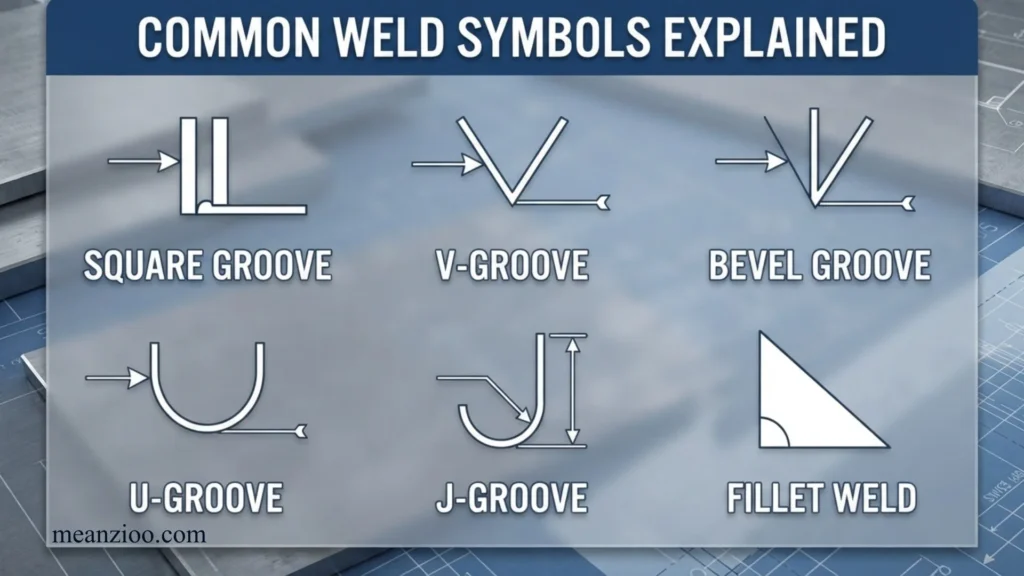
Learning the common symbols is the fastest way to become comfortable with welding drawings.
Fillet Weld Symbol
The fillet weld symbol is a triangle.
Fillet welds are widely used for:
- T-joints
- Lap joints
- Corner joints
- Structural connections
- General fabrication
The symbol tells you that a fillet weld is required, while dimensions and its position relative to the reference line provide additional information.
Because fillet welds are extremely common, the triangular symbol is one of the first welding symbols most people learn.
Square-Groove Weld Symbol
The square-groove symbol represents a joint in which the members have square edges rather than a V-shaped or curved groove preparation.
It can be used where the joint design does not require beveling the edges.
Additional information on the drawing may specify:
- Root opening
- Weld size
- Joint configuration
- Required penetration
- Other fabrication requirements
V-Groove Weld Symbol
A V-shaped symbol represents a V-groove weld.
The joint edges are prepared to create a V-shaped groove.
Depending on the design, additional information may specify:
- Groove angle
- Root opening
- Root face
- Groove depth
- Weld size
- Whether preparation is required on one or both sides
A V-groove is commonly used when joint preparation is needed to achieve the specified weld configuration or penetration.
Bevel-Groove Weld Symbol
A bevel-groove weld uses a joint in which one member has a beveled edge.
The symbol helps communicate the required groove configuration.
Bevel-groove symbols require careful attention to the arrow because the drawing can need to identify which member is prepared.
U-Groove Weld Symbol
The U-shaped symbol represents a U-groove weld.
A U-groove uses a curved joint preparation and can be useful for certain thicker-material applications where the joint design is intended to control weld-metal requirements.
The drawing can provide additional dimensions for the U-groove preparation.
J-Groove Weld Symbol
The J-shaped symbol represents a J-groove weld.
A J-groove has a curved preparation on one member while the other side remains relatively straight.
As with other groove symbols, the complete drawing determines the required preparation, dimensions, and welding requirements.
Plug Weld Symbol
A plug weld joins two members through a hole in one member.
The drawing can specify the dimensions and location of the hole and other requirements for the plug weld.
Plug welds can be used where access or joint configuration makes a conventional weld along the edge unsuitable.
Slot Weld Symbol
A slot weld is similar to a plug weld but uses an elongated slot instead of a round hole.
The welding symbol can communicate:
- Slot dimensions
- Weld size
- Location
- Spacing
- Number of slots
Spot Weld Symbol
A spot weld is commonly associated with resistance welding.
The symbol can be accompanied by dimensions or other information describing the required spot-weld size, spacing, and number.
Spot welding is particularly important in applications involving sheet metal and overlapping components.
Seam Weld Symbol
A seam weld represents a seam-welding requirement.
Depending on the application, seam welds may be continuous or otherwise specified by the drawing.
Dimensions and supplementary information determine exactly how the seam is to be produced.
Edge Weld Symbol
An edge weld joins components along their edges.
The symbol communicates the required edge-weld configuration, while additional dimensions can specify size or other characteristics.
Stud Weld Symbol
A stud weld is used to attach a stud or similar component to another material.
Its symbol and associated information identify the required stud-welding operation.
Also Check This Post:Commercial Auto Symbols: Complete Guide to Symbols 1–9 and 19
Weld Symbols Chart
The following quick-reference table is useful for beginners:
| Weld type | Basic symbol appearance | What it indicates |
| Fillet | Triangle | Fillet weld |
| Square groove | Square-type symbol | Square-groove preparation |
| V-groove | V | V-groove weld |
| Bevel groove | Beveled shape | Bevel-groove weld |
| U-groove | U | U-groove preparation |
| J-groove | J | J-groove preparation |
| Plug weld | Plug symbol | Weld through a hole |
| Slot weld | Slot symbol | Weld through an elongated slot |
| Spot weld | Circle | Spot weld |
| Seam weld | Seam symbol | Seam weld |
| Edge weld | Edge-weld symbol | Edge weld |
| Stud weld | Stud symbol | Stud attachment |
The symbol itself is only one part of the complete welding instruction. Always check dimensions, location, supplementary symbols, notes, and the governing standard.
Arrow Side and Other Side
One of the most important concepts in reading weld symbols is determining which side of the joint should receive the weld.
Under AWS A2.4 conventions, information applicable to the arrow side is placed below the reference line, while information for the other side is placed above the reference line.
In simple AWS-style notation:
- Below the reference line = arrow side
- Above the reference line = other side
- Symbols on both sides = weld requirements on both sides, when the complete symbol specifies this arrangement
This is one of the most common areas of confusion for beginners.
Why Arrow-Side Interpretation Matters
Consider a T-joint. If the drawing specifies a fillet weld on only one side, putting the weld on the wrong side can produce a joint that does not meet the drawing requirement.
Therefore, do not simply recognize the triangle and start welding.
First determine:
- What joint is being referenced?
- Where does the arrow point?
- Is the symbol above or below the reference line?
- Does the drawing specify welding on one side or both?
- Are there additional notes or dimensions?
AWS specifically highlights the arrow-side/other-side convention as critical to correctly interpreting welding symbols.
AWS and ISO Weld Symbols: What Is the Difference?
This is an important topic because AWS and ISO welding-symbol systems should not be treated as identical.
AWS A2.4 is widely used in American welding and engineering practice. ISO 2553 is an international standard for symbolic representation of welded joints on technical drawings. ISO 2553 recognizes two different approaches to identifying arrow-side and other-side welds: System A uses a dual reference line, while System B uses a single reference line.
This means a welder who is familiar with one system should not automatically interpret every drawing using the same rules.
AWS-Style Convention
In the commonly used AWS A2.4 approach:
- Below the reference line generally indicates the arrow side.
- Above the reference line generally indicates the other side.
AWS A2.4:2020 provides the conventions used to communicate welding requirements among designers, welders, and inspectors.
ISO 2553
ISO 2553 can use a dual reference-line system in System A, where the relationship between the weld symbol and the reference lines identifies the side of the joint.
Because ISO 2553 also defines System B, the exact drawing convention must be identified rather than assumed.
Best Practice
When reading a professional drawing:
- Check the title block.
- Look for the referenced standard.
- Determine whether the drawing uses AWS, ISO, or another applicable system.
- Follow that standard consistently.
- If the symbol remains ambiguous, consult the drawing notes, engineer, welding procedure, or applicable standard.
Weld Size and Dimensions
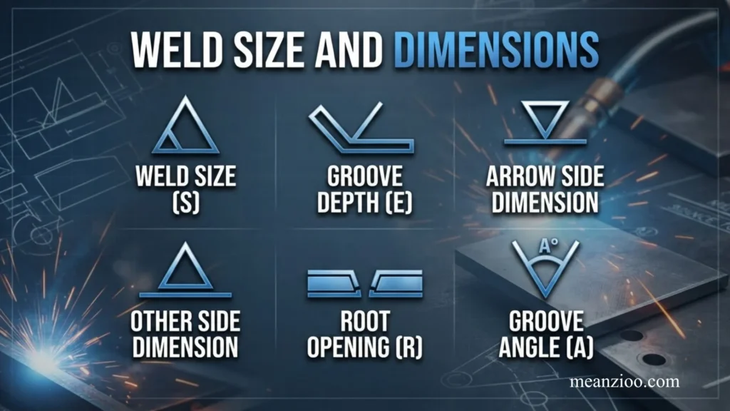
A weld symbol can specify much more than the type of weld.
Numbers placed around the symbol provide dimensional requirements.
For example, a drawing may specify:
- Fillet weld size
- Groove depth
- Weld length
- Number of welds
- Pitch
- Root opening
- Groove angle
- Other dimensions
Fillet Weld Size
For a fillet weld, a dimension may specify the required size of the fillet.
However, the meaning of a dimension depends on its position and the applicable symbol.
This is why simply seeing a number next to a triangle is not enough. You need to understand where the number is located and what the drawing standard says.
Weld Length
A dimension can specify how long a weld must be.
For a continuous weld, the drawing may indicate a specific length or allow the weld to extend along the specified joint.
For intermittent welds, the length of individual segments becomes especially important.
Pitch
Pitch generally describes the center-to-center spacing between adjacent weld segments in an intermittent weld.
For example, a drawing might specify a weld segment length together with a pitch value. The welder must understand that these are two different pieces of information.
Intermittent Weld Symbols
An intermittent weld consists of separate weld segments rather than one continuous weld.
They are often used when a continuous weld is unnecessary for the design or when the drawing specifically calls for spaced welds.
An intermittent weld specification may communicate:
- Length of each weld segment
- Pitch
- Number of segments
- Location
- Whether the segments are staggered
Staggered and Chain Intermittent Welds
Intermittent welds can be arranged in different patterns.
A chain intermittent weld places weld segments on opposite sides in a corresponding pattern.
A staggered intermittent weld offsets the segments on opposite sides.
These arrangements should be interpreted from the complete welding symbol rather than guessed from the weld shape alone.
Supplementary Weld Symbols
Supplementary symbols add information to the basic weld symbol.
Weld-All-Around Symbol
A small circle at the appropriate location around the arrow/reference-line junction can indicate that the weld is required all around the joint.
This is useful when the weld must continue around the entire joint rather than stopping at a particular section.
Field Weld Symbol
A field-weld symbol indicates that the weld is to be made at the job site or installation location rather than in the fabrication shop.
This can matter because transportation, access, assembly sequence, and inspection requirements can differ between shop and field welding.
Contour Symbols
Contour symbols communicate the desired shape of the finished weld face.
Common contour descriptions include:
- Flush
- Convex
- Concave
A contour symbol can be accompanied by a finish designation that provides additional information about how the weld surface should be finished.
Finish Information
A drawing may specify how the weld should be finished, such as by:
- Grinding
- Machining
- Chipping
- Other specified methods
The exact finish designation should be interpreted according to the applicable standard.
What Does the Tail of a Weld Symbol Mean?
The tail is optional and can contain additional information that is not efficiently represented by the basic weld symbol.
A tail may reference:
- Welding process
- Welding procedure
- Specification
- Code
- Welding Procedure Specification (WPS)
- Other notes
For example, instead of writing a long process instruction next to every weld, a drawing may use the tail to reference a particular procedure or process designation.
Always check the tail when one is present.
How to Read Weld Symbols Step by Step
If you are learning blueprint reading, the following method provides a practical way to interpret a welding symbol.
Step 1: Identify the Applicable Standard
Before interpreting complicated symbols, determine whether the drawing follows AWS, ISO, or another standard.
This prevents you from applying the wrong side-designation convention.
Step 2: Find the Joint
Follow the arrow to determine which joint the welding symbol references.
Do not assume that the nearest visible joint is automatically the intended joint.
Step 3: Locate the Reference Line
Find the horizontal or otherwise designated reference line carrying the welding information.
Step 4: Identify the Basic Weld Symbol
Determine the weld type from its graphical shape.
For example:
- Triangle = fillet weld
- V = V-groove
- U = U-groove
- J = J-groove
Step 5: Determine the Side
Check the position of the weld symbol relative to the reference line.
Under AWS conventions:
- Below = arrow side
- Above = other side
For ISO drawings, identify which ISO system is being used before interpreting the reference lines.
Step 6: Read the Dimensions
Look for numbers around the symbol.
Determine whether they represent:
- Size
- Length
- Pitch
- Depth
- Angle
- Root opening
- Other requirements
Step 7: Check for Supplementary Symbols
Look for:
- All-around symbol
- Field-weld symbol
- Contour
- Finish
- Backing
- Other supplementary information
Step 8: Read the Tail
If a tail is present, check whether it identifies:
- Process
- WPS
- Specification
- Code
- Other instructions
Step 9: Read the Drawing Notes
Do not stop at the welding symbol.
The drawing may contain general notes, material specifications, welding procedures, inspection requirements, or acceptance criteria that are essential to the job.
Also Check This Post:Symbols of Ireland: 15 Irish Symbols, Their Meanings, History, and Cultural Significance
Practical Examples of Reading Weld Symbols
Example 1: Fillet Weld on One Side
Suppose a T-joint has a triangular fillet symbol below an AWS-style reference line.
The basic interpretation is:
- Triangle = fillet weld
- Below the line = arrow side
- Any nearby number may specify weld size
- Additional symbols may specify length, contour, or other requirements
The welder should therefore examine the complete callout rather than simply seeing “triangle = fillet.”
Example 2: Fillet Weld on Both Sides
If fillet-weld symbols are shown on both sides of the reference line, the drawing can indicate a fillet weld requirement on both sides of the joint.
The dimensions must still be checked to determine whether the two welds are identical or have different requirements.
Example 3: Intermittent Fillet Weld
Suppose a fillet weld symbol is accompanied by length and pitch information.
The welder must distinguish between:
- Length of each weld segment
- Center-to-center spacing
Confusing those two dimensions can produce a weld pattern that differs from the design.
Example 4: Weld-All-Around Requirement
If the appropriate all-around supplementary symbol is present, the welding requirement extends around the joint as specified by the symbol.
The welder should then inspect the drawing carefully to determine exactly which joint features are included.
Common Mistakes When Reading Weld Symbols
Understanding the common errors can help prevent costly fabrication problems.
Mistake 1: Looking Only at the Weld Shape
A triangle tells you that the weld is a fillet weld, but it does not tell you everything about the weld.
You still need to check:
- Side
- Size
- Length
- Spacing
- Contour
- Finish
- Additional notes
Mistake 2: Confusing Arrow Side and Other Side
This is one of the most important errors to avoid.
Under AWS conventions, the symbol’s position relative to the reference line determines arrow-side or other-side significance.
Mistake 3: Assuming Every Number Is Weld Size
A number can represent different requirements depending on its location and the type of weld symbol.
Always interpret the number in context.
Mistake 4: Ignoring Pitch
With intermittent welds, weld length and pitch are different measurements.
Ignoring pitch can result in incorrect spacing.
Mistake 5: Ignoring the Tail
A tail can contain process, specification, or procedure information.
Skipping it can mean missing an important welding requirement.
Mistake 6: Mixing AWS and ISO Rules
A drawing based on ISO 2553 should not automatically be interpreted using AWS A2.4 conventions.
ISO 2553 explicitly provides more than one reference-line approach, while AWS has its own established conventions.
Mistake 7: Ignoring Drawing Notes
The welding symbol is part of the drawing, not the entire drawing.
General notes and referenced specifications may contain requirements that are not repeated beside every weld.
Weld Symbols vs. Welding Symbols
These terms are often used interchangeably in casual conversation, but there is a useful distinction.
A weld symbol is the graphical mark representing a specific weld type.
A welding symbol is the complete notation containing the weld symbol plus the reference line, arrow, dimensions, supplementary symbols, and other information.
For example, the triangle is the basic fillet-weld symbol. A complete welding symbol might combine that triangle with a reference line, arrow, weld size, weld length, contour symbol, and tail.
Understanding this distinction makes technical discussions easier.
Weld Symbol vs. Joint Type
Another common source of confusion is the difference between a joint type and a weld type.
Common joint configurations include:
- Butt joint
- Lap joint
- T-joint
- Corner joint
- Edge joint
Weld types include:
- Fillet weld
- Groove weld
- Plug weld
- Slot weld
- Spot weld
- Seam weld
- Stud weld
- Edge weld
A T-joint, for example, does not automatically mean that the weld must be a fillet weld. The actual welding symbol on the drawing determines the specified weld.
Why Weld Symbols Matter for Inspection
Welding inspectors need to understand symbols because inspection involves comparing the completed work against the drawing requirements.
A welding symbol can establish requirements related to:
- Weld type
- Location
- Size
- Length
- Spacing
- Contour
- Finish
- Supplementary requirements
The inspector therefore needs to interpret the complete callout before deciding whether a weld meets the specified requirement.
This is also why symbol interpretation is important for quality assurance and fabrication documentation.
Welding Symbols on Engineering Drawings
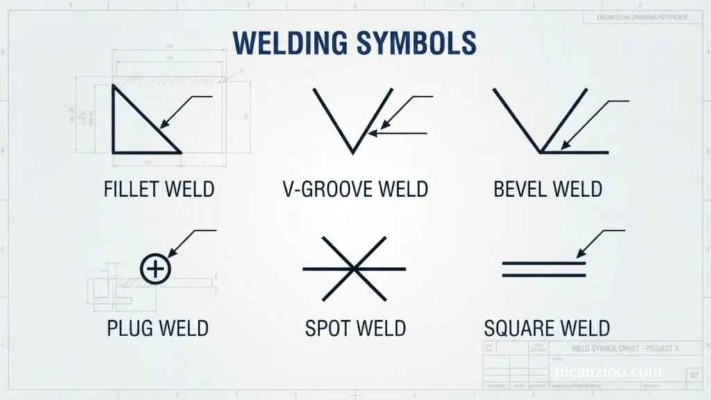
Welding symbols can appear on many types of engineering drawings, including:
- Structural steel drawings
- Machine-part drawings
- Automotive drawings
- Pressure-equipment drawings
- Piping drawings
- Fabrication drawings
- Architectural metalwork drawings
- Manufacturing drawings
The exact standard used can vary according to the industry, country, customer, and project.
Always follow the standard identified by the drawing or project documentation.
AWS A2.4 and ISO 2553: Which One Should You Use?
There is no universal answer that every project should use one system.
Use the standard required by the project.
AWS A2.4 is particularly important when working with drawings and welding codes that use AWS/ANSI conventions. AWS identifies A2.4:2020 as its standard for symbols for welding, brazing, and nondestructive examination.
ISO 2553:2019 defines symbolic representation of welded joints on technical drawings and is used internationally. It covers information concerning weld geometry, manufacture, quality, and testing.
When a project specifies a particular standard, that standard should take priority over a generic online chart.
Frequently Asked Questions About Weld Symbols
What is a weld symbol?
A weld symbol is a standardized graphical mark used on a technical drawing to identify a particular weld or joint-preparation requirement.
What is the most common weld symbol?
The fillet weld symbol, represented by a triangle, is one of the most commonly encountered weld symbols in fabrication and structural drawings.
What does a triangle mean in welding symbols?
A triangle generally represents a fillet weld in common AWS and ISO welding-symbol systems.
What does a V mean on a welding drawing?
A V-shaped symbol represents a V-groove weld. Additional dimensions may define groove angle, root opening, depth, and other requirements.
What does the line in a weld symbol mean?
The reference line provides the main framework for the welding symbol. Weld symbols, dimensions, and other information are positioned around it according to the applicable standard.
What does a weld symbol below the line mean?
Under the AWS A2.4 convention, a weld symbol below the reference line indicates the arrow side of the joint.
What does a weld symbol above the line mean?
Under the AWS A2.4 convention, a weld symbol above the reference line indicates the other side of the joint.
What does a circle at the reference line mean?
A circle used in the appropriate location can indicate a weld-all-around requirement.
What does a flag on a welding symbol mean?
A field-weld symbol indicates that the weld is to be performed at the field or installation site rather than in the fabrication shop.
What does the tail of a welding symbol indicate?
The tail can provide additional information such as a welding process, specification, procedure, or other reference.
What is the difference between AWS and ISO weld symbols?
AWS A2.4 and ISO 2553 are separate standards with related but not identical conventions. ISO 2553 recognizes both dual-reference-line and single-reference-line systems, so the applicable standard and system should always be identified before interpreting a drawing.
Are weld symbols universal?
They are standardized, but not all standards use exactly the same conventions. AWS, ISO, and other standards can differ in specific details. Always use the standard specified by the project.
How do I learn welding symbols quickly?
Start with the reference line, arrow, fillet symbol, major groove symbols, arrow-side/other-side rules, dimensions, intermittent welds, and supplementary symbols. Then practice reading complete welding callouts on real engineering drawings.
Final Takeaway
Weld symbols provide a compact language for communicating welding requirements on technical drawings. To read them correctly, you need to understand more than the individual symbol.
Start with the reference line and arrow, identify the basic weld symbol, determine the applicable side of the joint, read the dimensions, check supplementary symbols, inspect the tail, and finally review the drawing notes and applicable welding standard.
The most important lesson is to read the complete welding symbol rather than interpreting one graphic in isolation.
For AWS-based drawings, AWS A2.4 provides the relevant standardized conventions. For international drawings, ISO 2553 may apply, and its reference-line systems should be understood before interpreting arrow-side and other-side information.
When a weld symbol is unclear on an actual fabrication project, do not guess. Check the governing standard, drawing notes, welding procedure, or responsible engineering authority before welding.
Also Check This Post:Catholic Church Symbols: Complete Guide to Their Meanings, History, and Significance

Hi, I’m Charlotte Hayes. I love writing about the newest English slang, pop culture phrases, and digital communication. I spend my time exploring how language evolves across social media, gaming, and everyday conversations. I enjoy sharing easy-to-understand guides that help learners keep up with modern English. My goal is to make every article useful, accurate, and enjoyable for readers around the world.
Books:
- Everyday Slang Dictionary
- Fluent Through Informal English
 Ryan Mitchell